
IoTaWatt Home Energy Monitor Installation
I've been looking for a home energy monitoring solution for a while now, and finally decided on the IoTaWatt. It has several advantages (in my mind), primary among them being that the IoTaWatt system is open source and is very well documented by its creators. Additionally, other more user-friendly energy monitors like the Sense (affiliate link) have an auto-sensing feature that, from the reviews I've read, isn't all that accurate. Full disclosure, I have no affiliation with IoTaWatt, and purchased everything here myself.
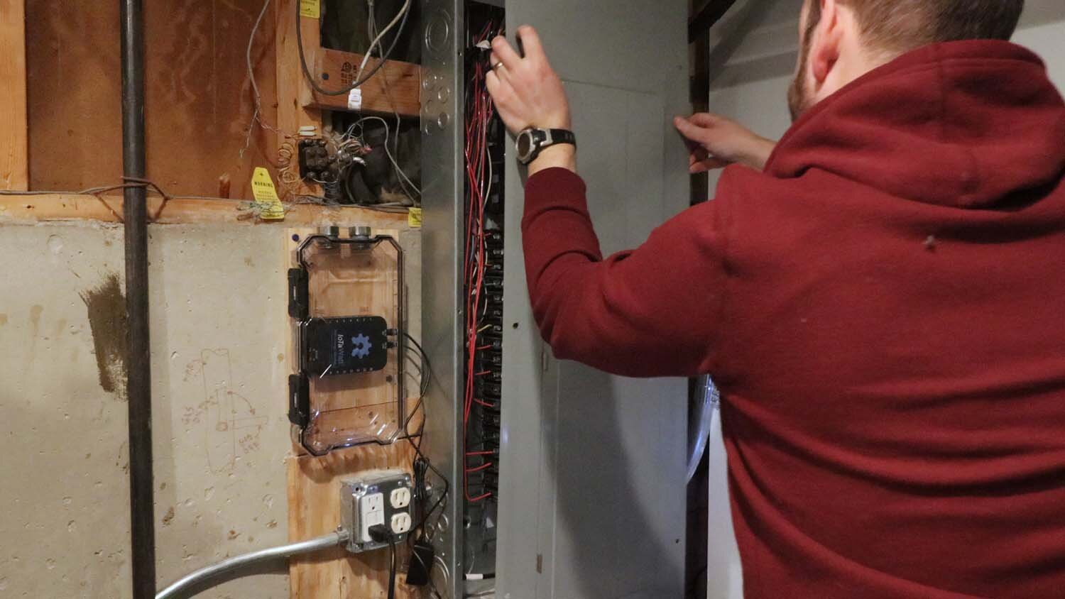
This article covers the physical installation of my IoTaWatt device, which involves clamping a number of current transformers to live electrical circuits in my electrical panel. Having worked around live circuits, this is something I'm comfortable with and have the know-how to handle. If this does not describe you, or if this is something you're not comfortable with, hire an electrician. I cannot gauge your personal comfort level or safety preferences.
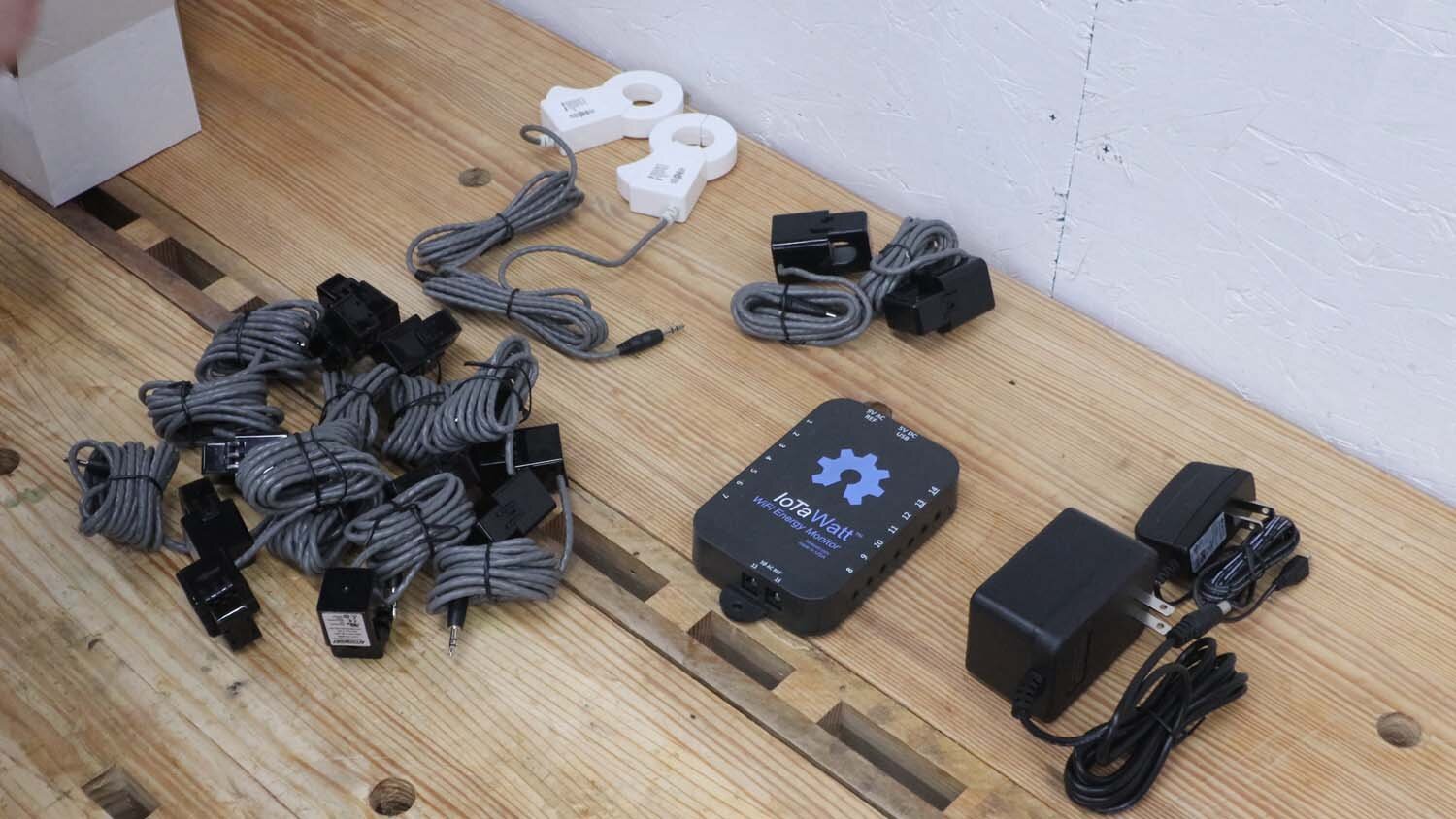
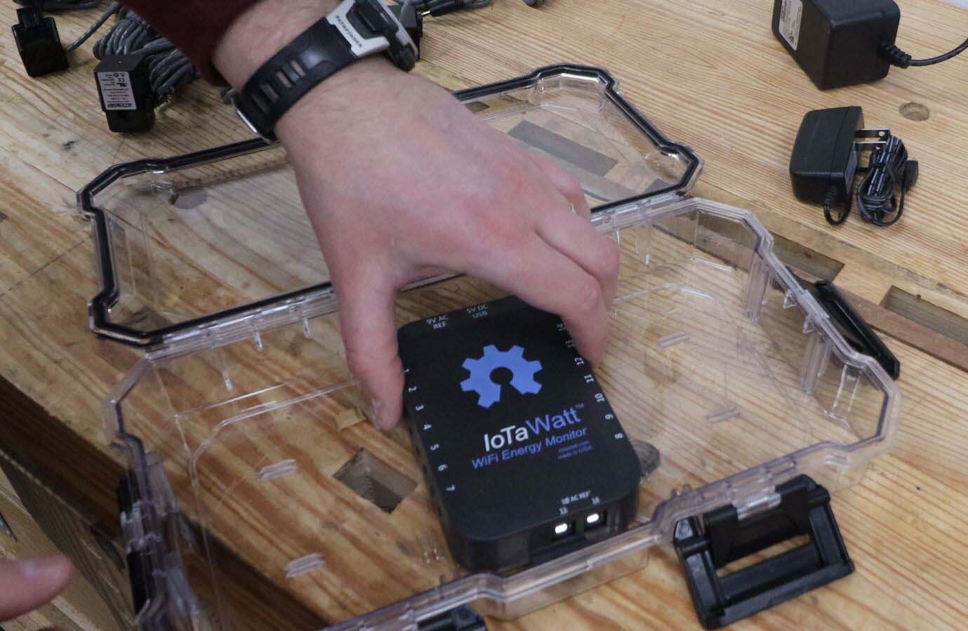
The IoTaWatt is made up of a central unit that processes incoming data, which receives signals from a variety of current transformers that are hooked up to electrical circuits. I don't know all the science behind them, but the current transformers sense the magnetic field around a wire and transform that into an amperage reading. Multiplying the amperage times a reference voltage, the IoTaWatt can then express the power used by the circuit. You can read more about how these work on the IoTaWatt website.
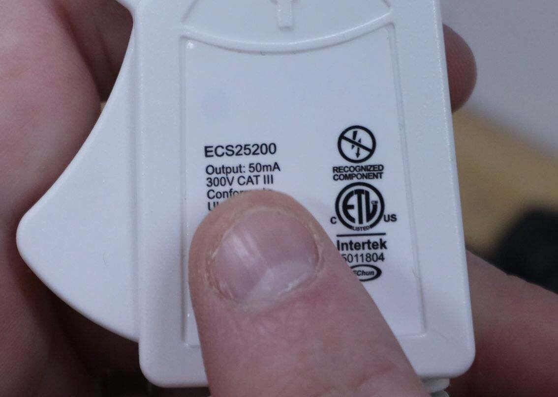
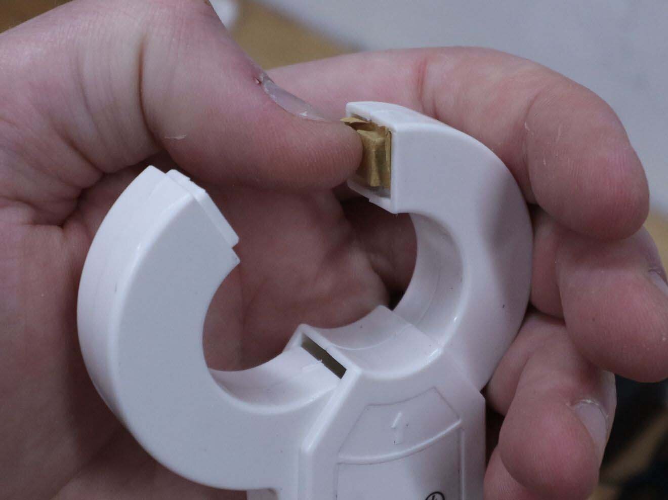
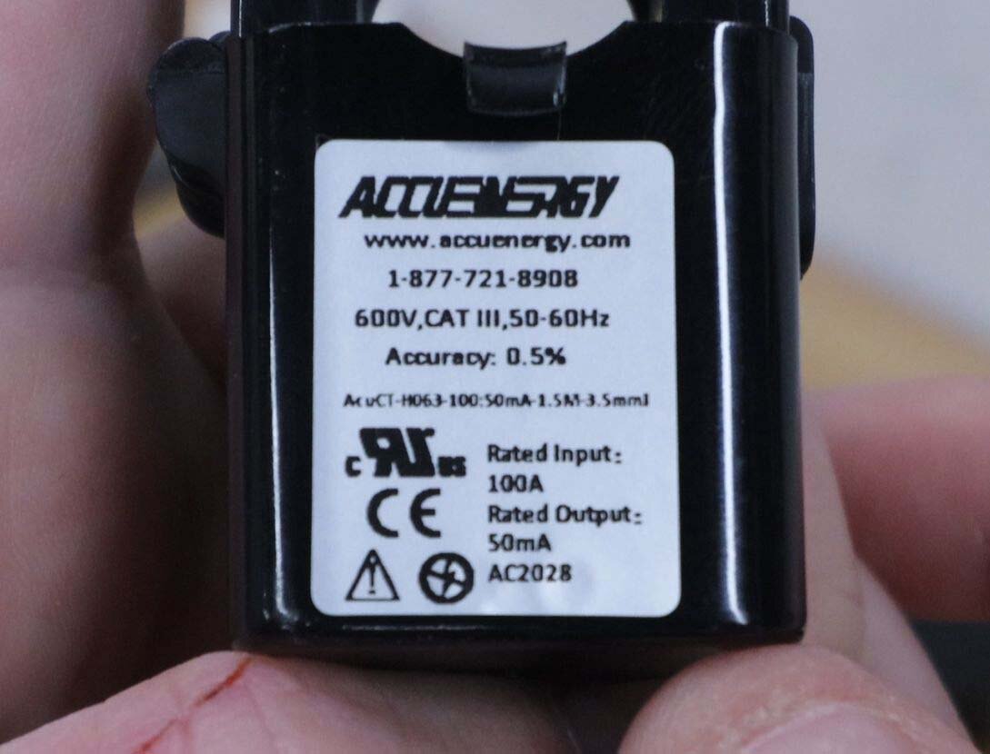
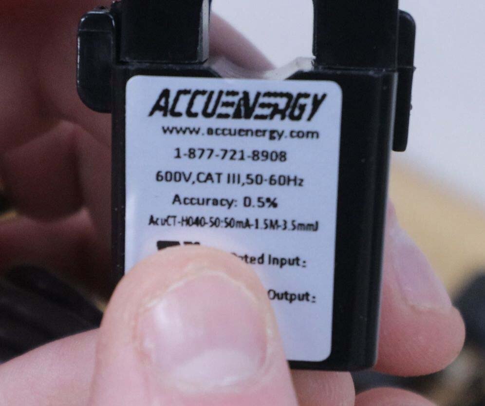
Your configuration will likely be different than mine, but for my panel I bought two 200-amp CTs for the main power feed, two 100-amp CTs for my workshop subpanel, and ten 50-amp CTs for other circuits in my house. When you unwrap these, you'll want to note down the model number for the CTs you're using, as these are used by the IoTaWatt later in setup. Also note that some of these CTs may have a piece of protective paper inside the clamping surfaces, which will need to be removed before use.
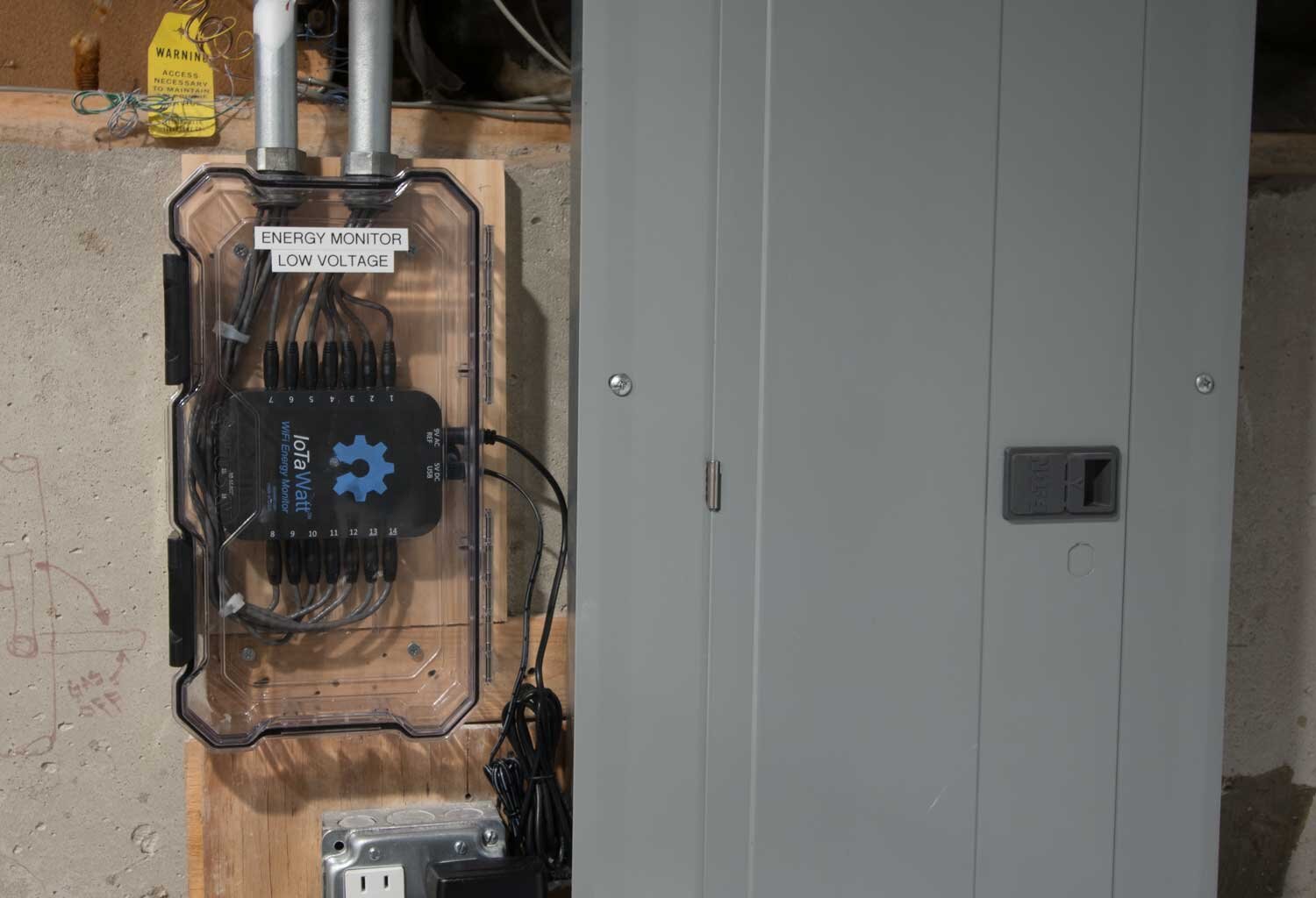
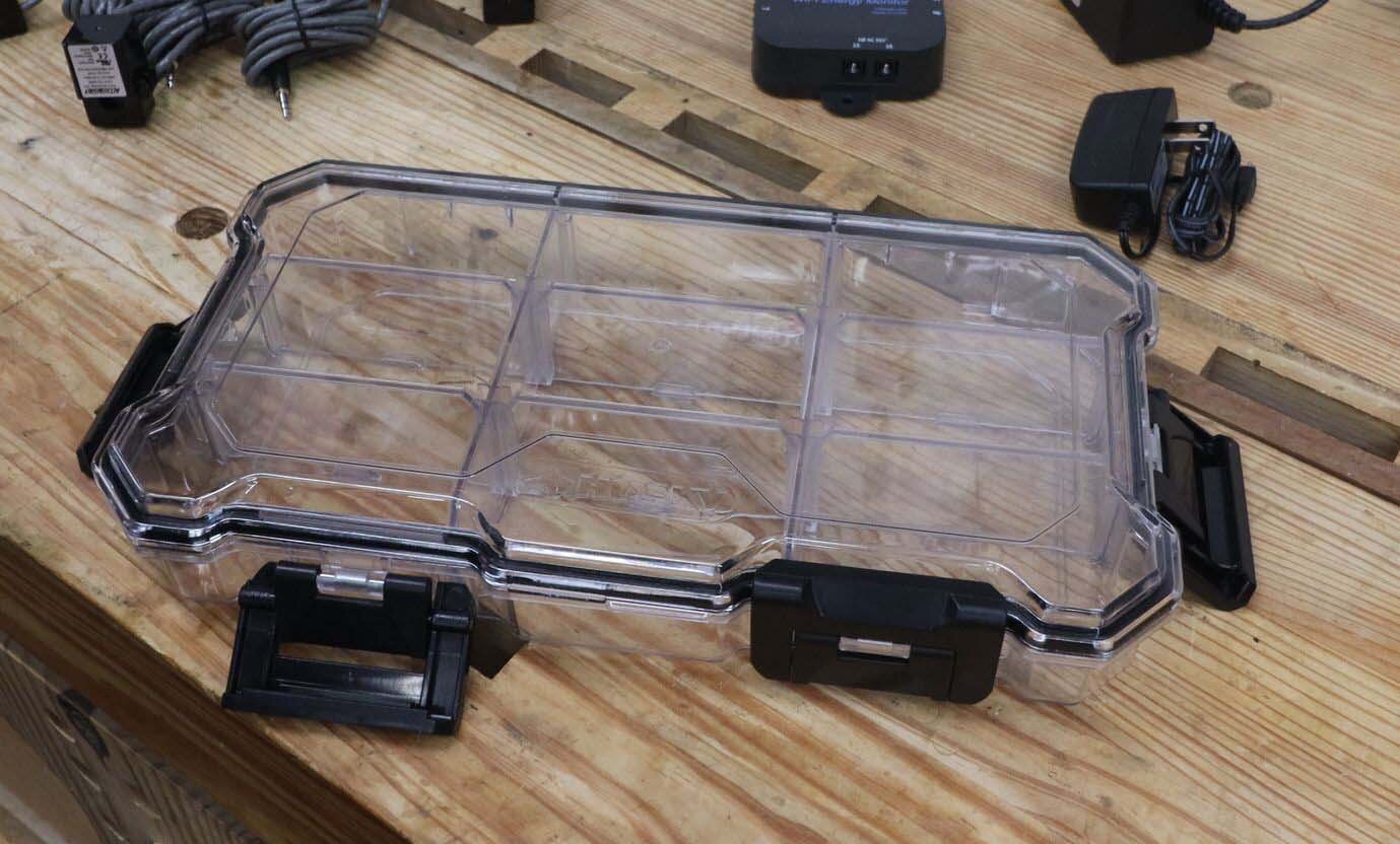
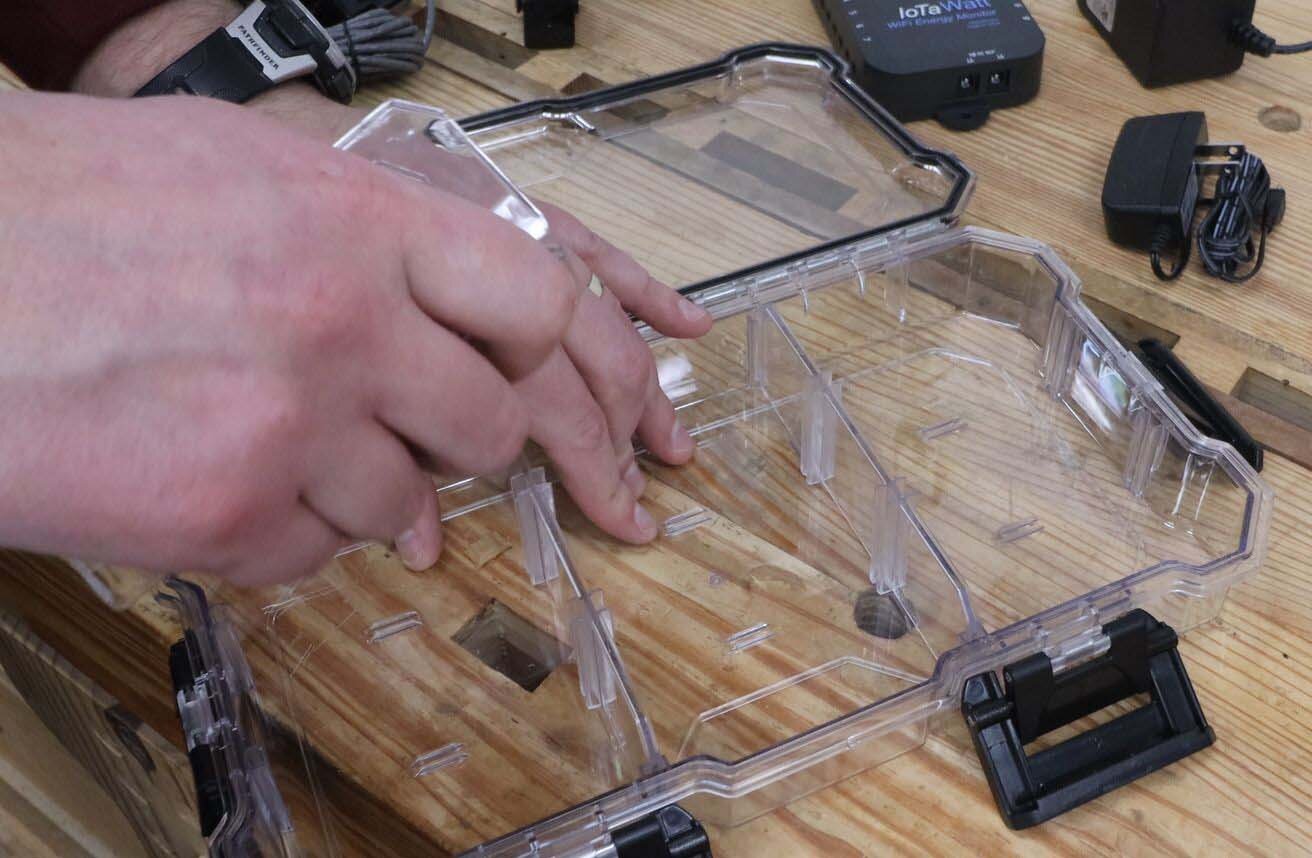
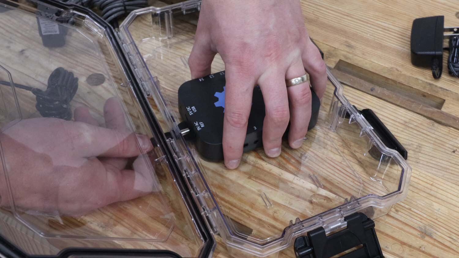
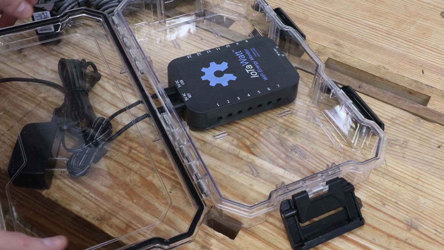
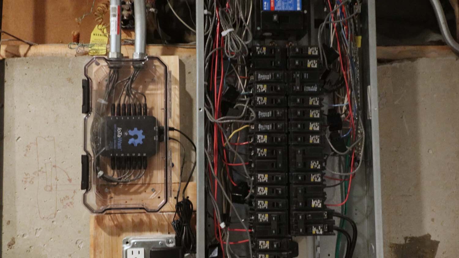
I've seen installs where these are just mounted to a piece of plywood with the wires all sticking out, but that's a bit messy for my taste. To keep the dust out, I'm keeping my IoTaWatt inside a clear plastic case that I got at the home center. This one is meant to be used to store parts, so I'm taking out the dividers.
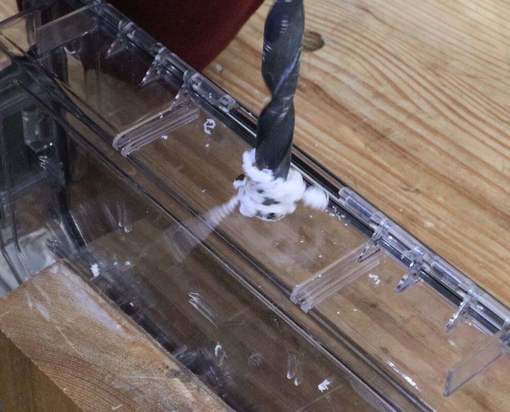
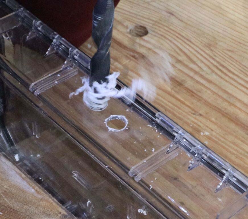
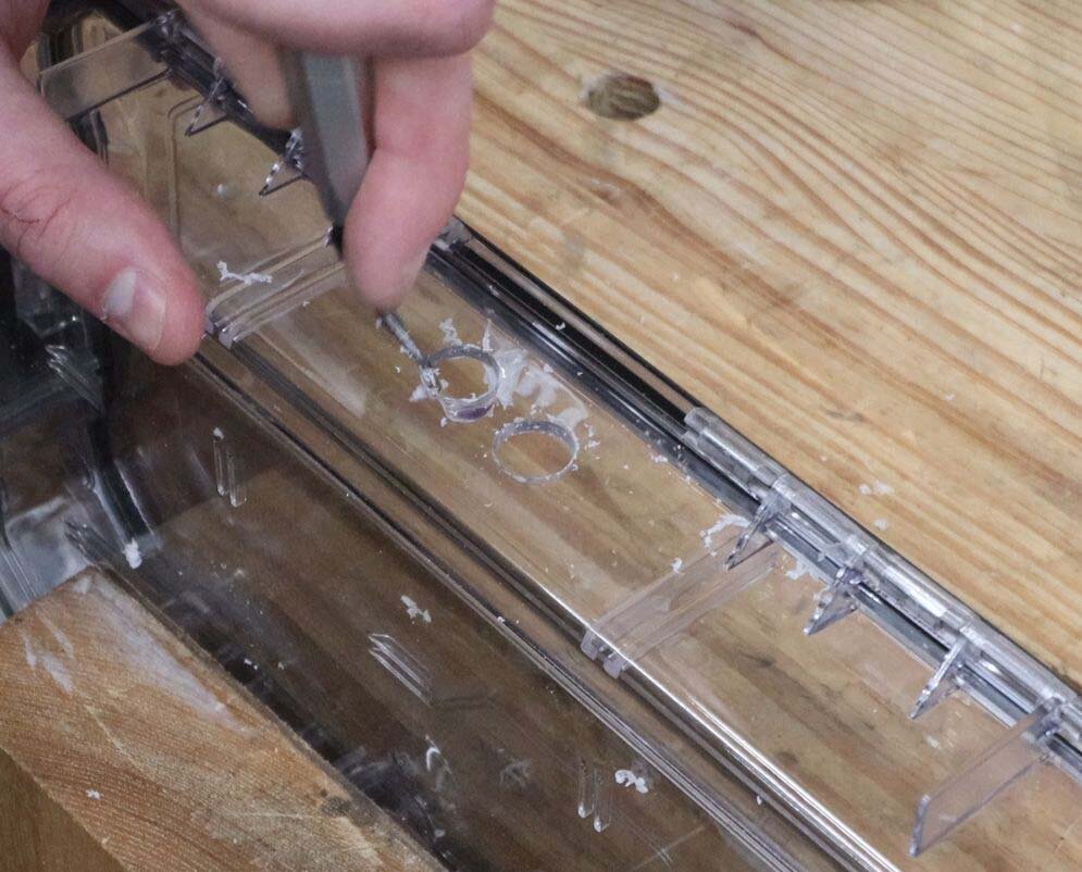
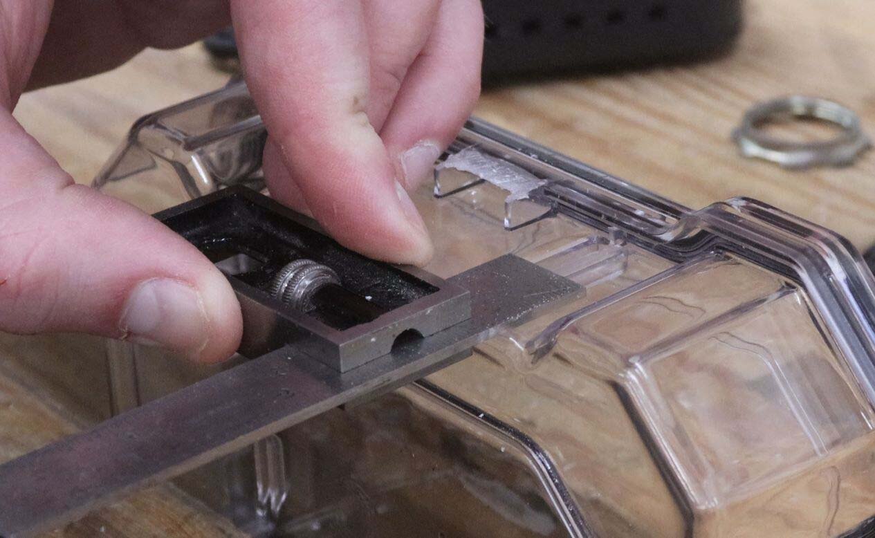
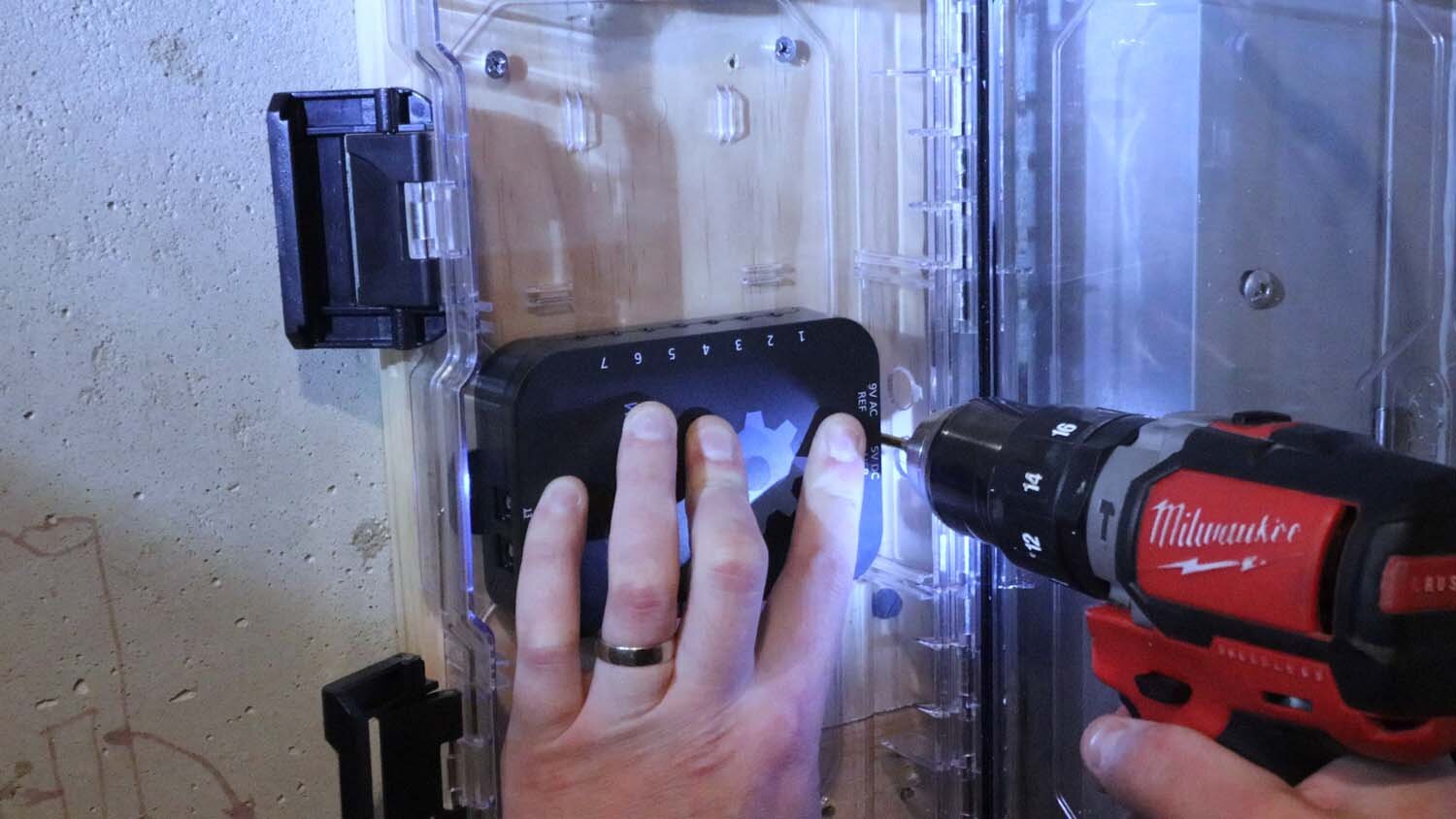
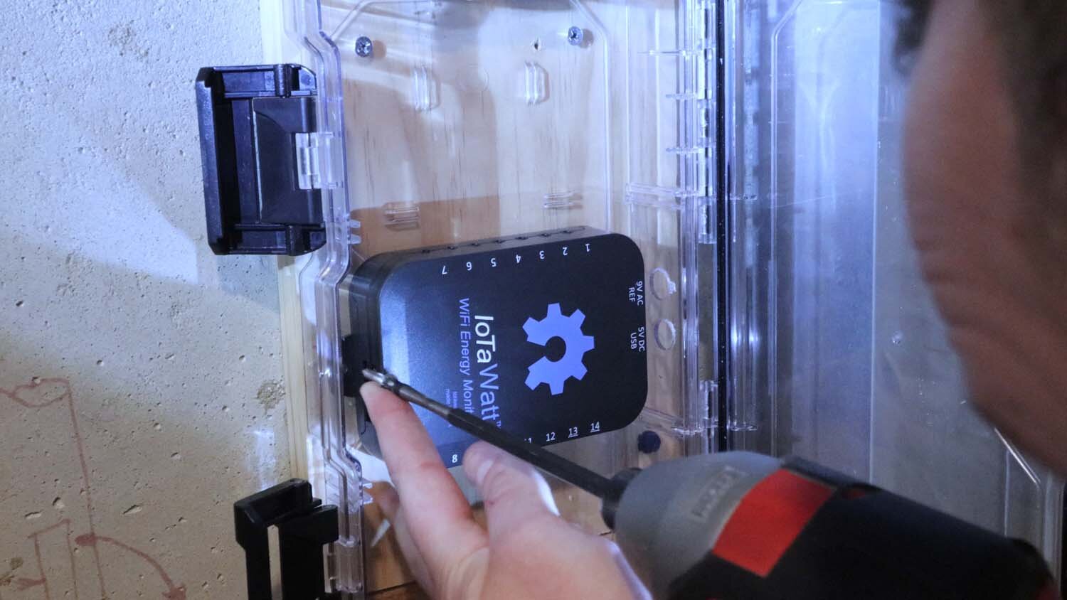
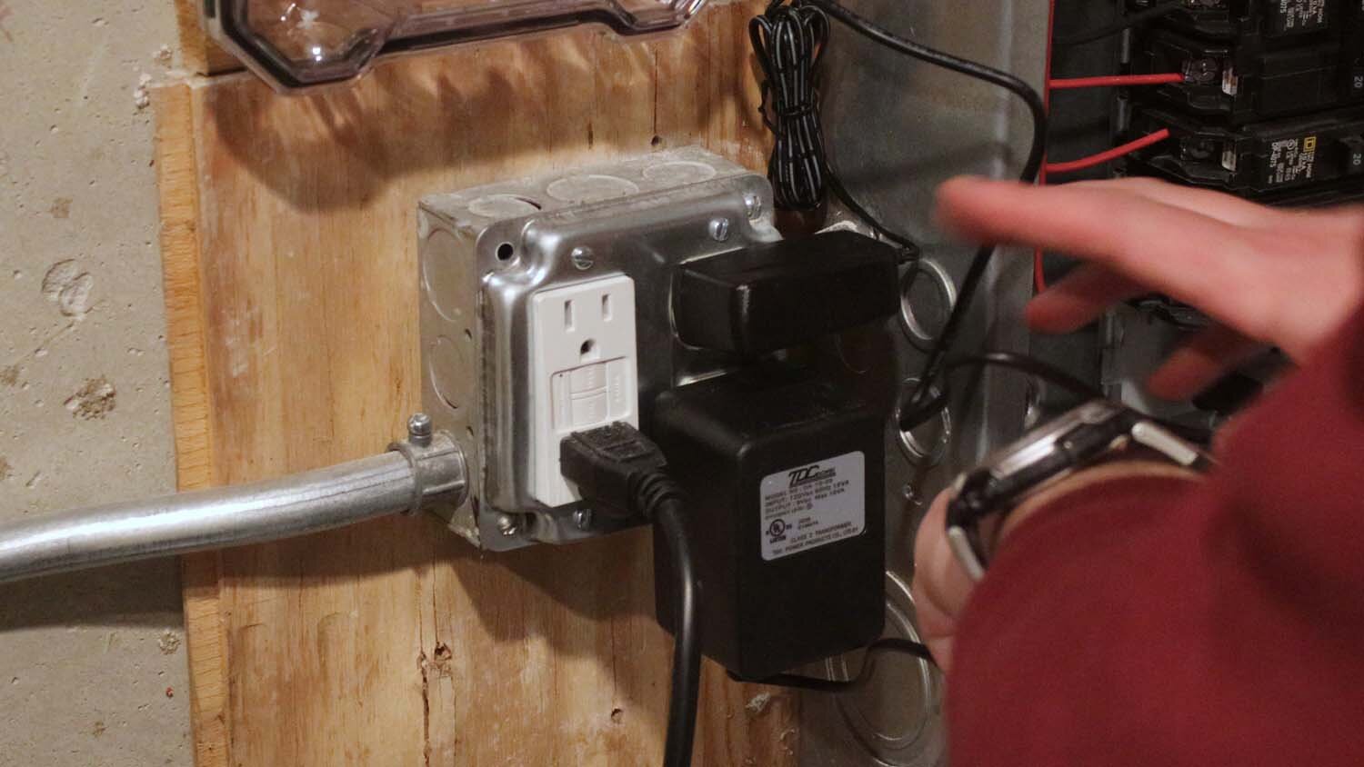
The IoTaWatt is powered by a USB charger and also takes input from a 9-volt source. I drilled two holes in the plastic box to allow these to pass through. I then used a deburring tool to remove the leftover bits of plastic on the holes.
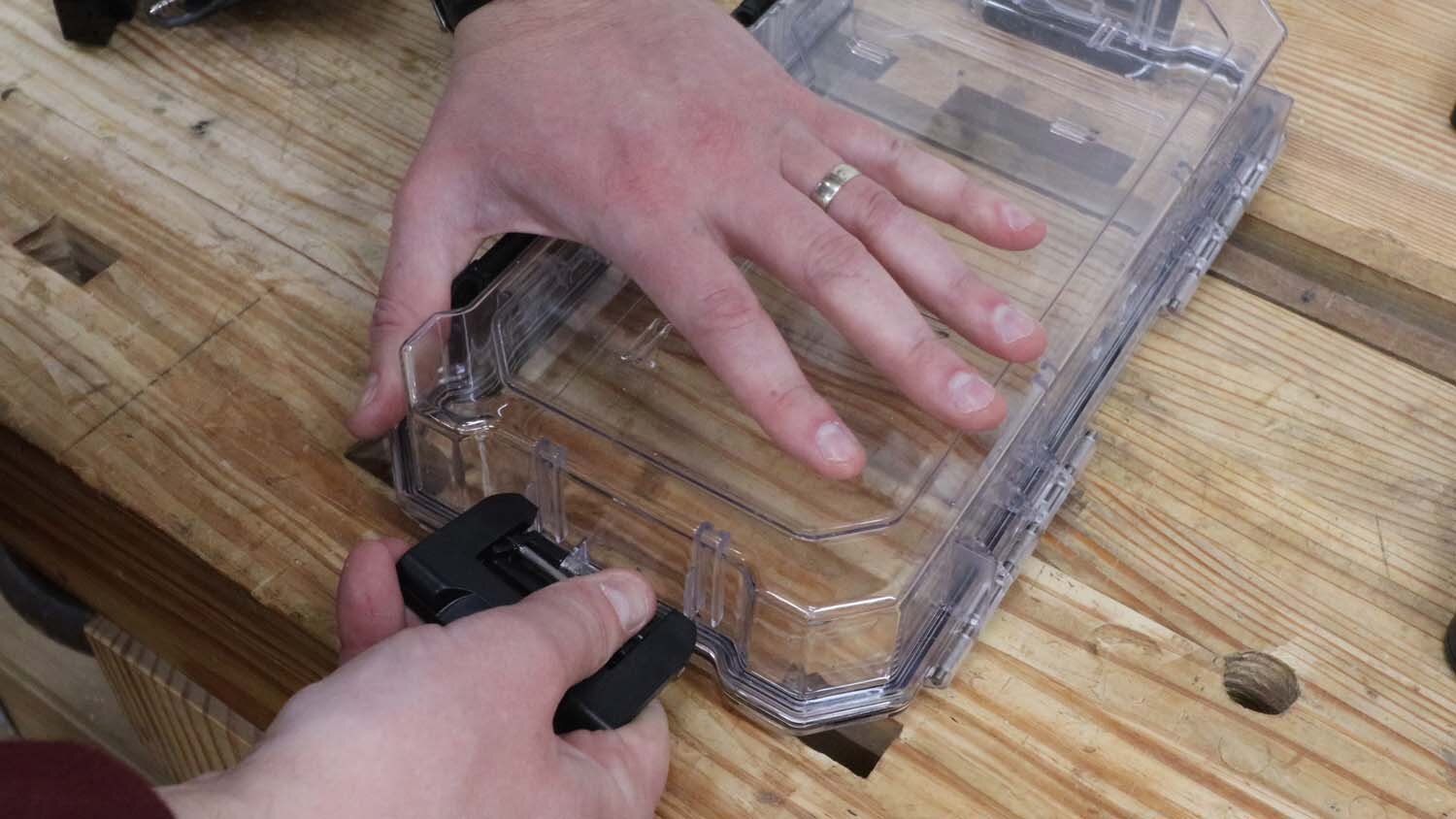
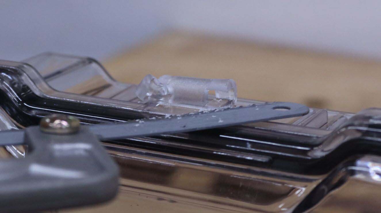
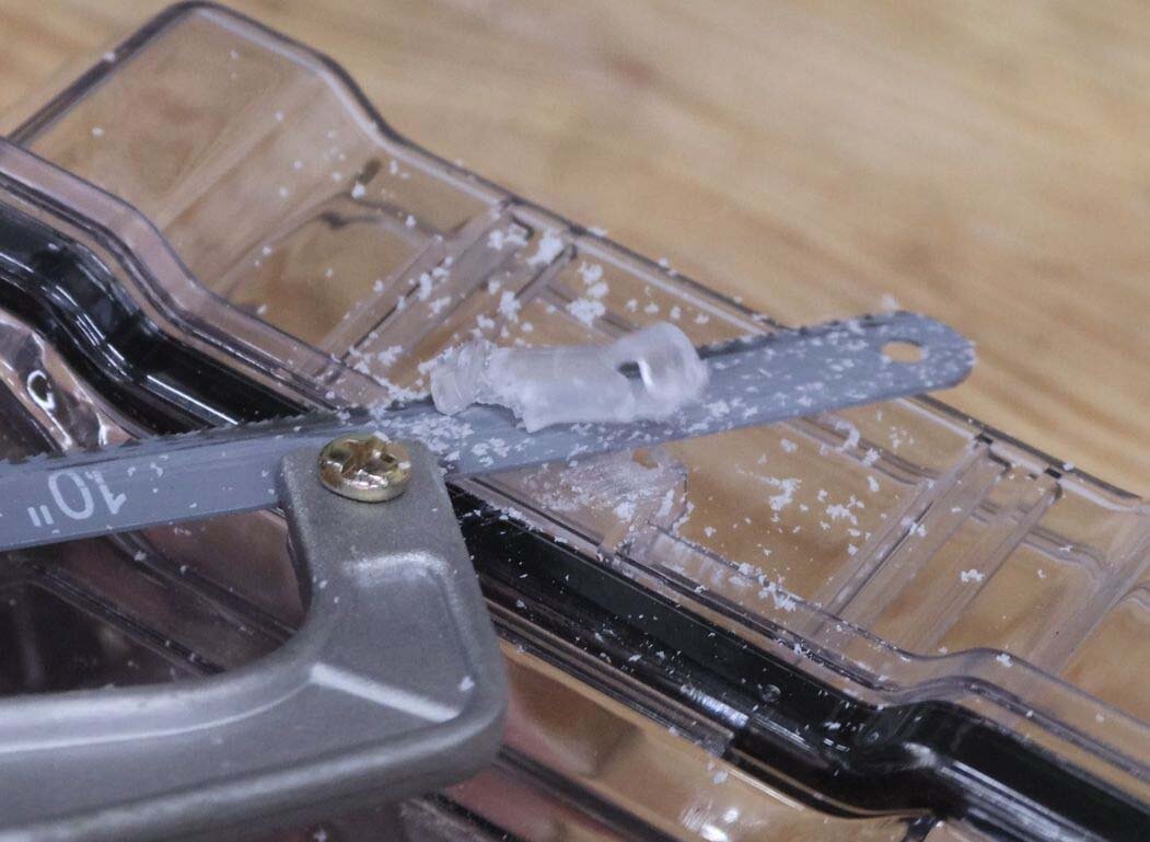
This box doesn't really need all four clasps, so I removed two of them by twisting them off and breaking the plastic. I then removed the leftover plastic parts of the hinge with a hacksaw.
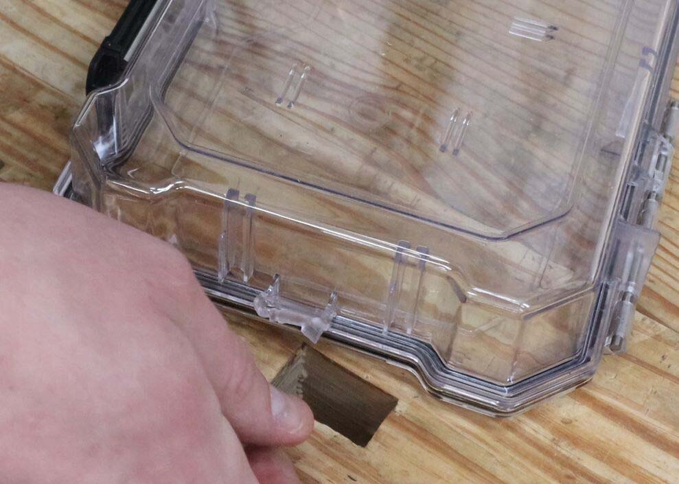
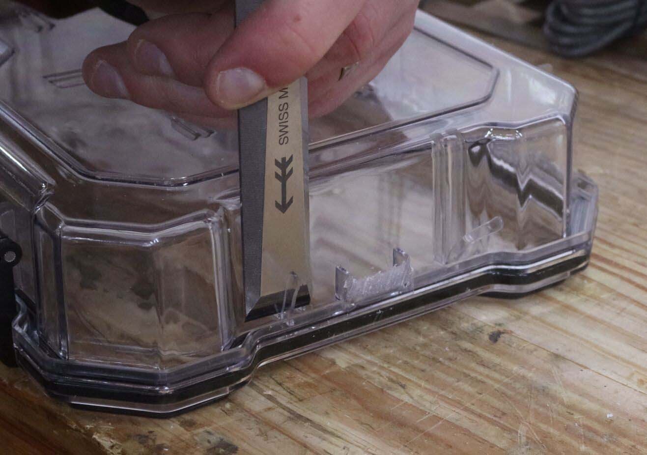
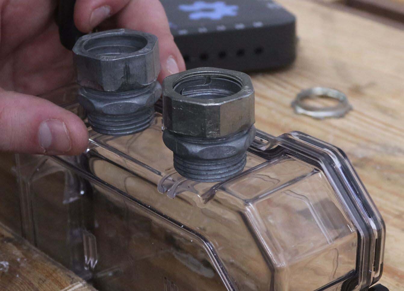
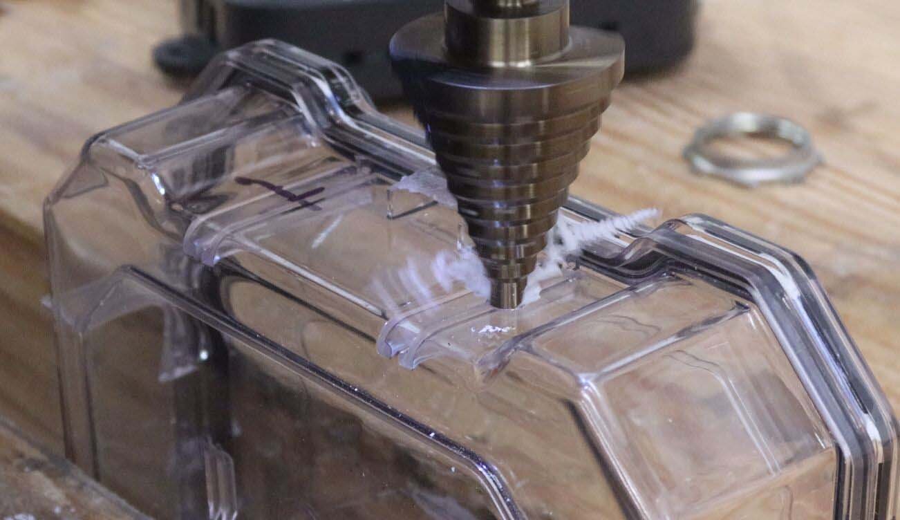
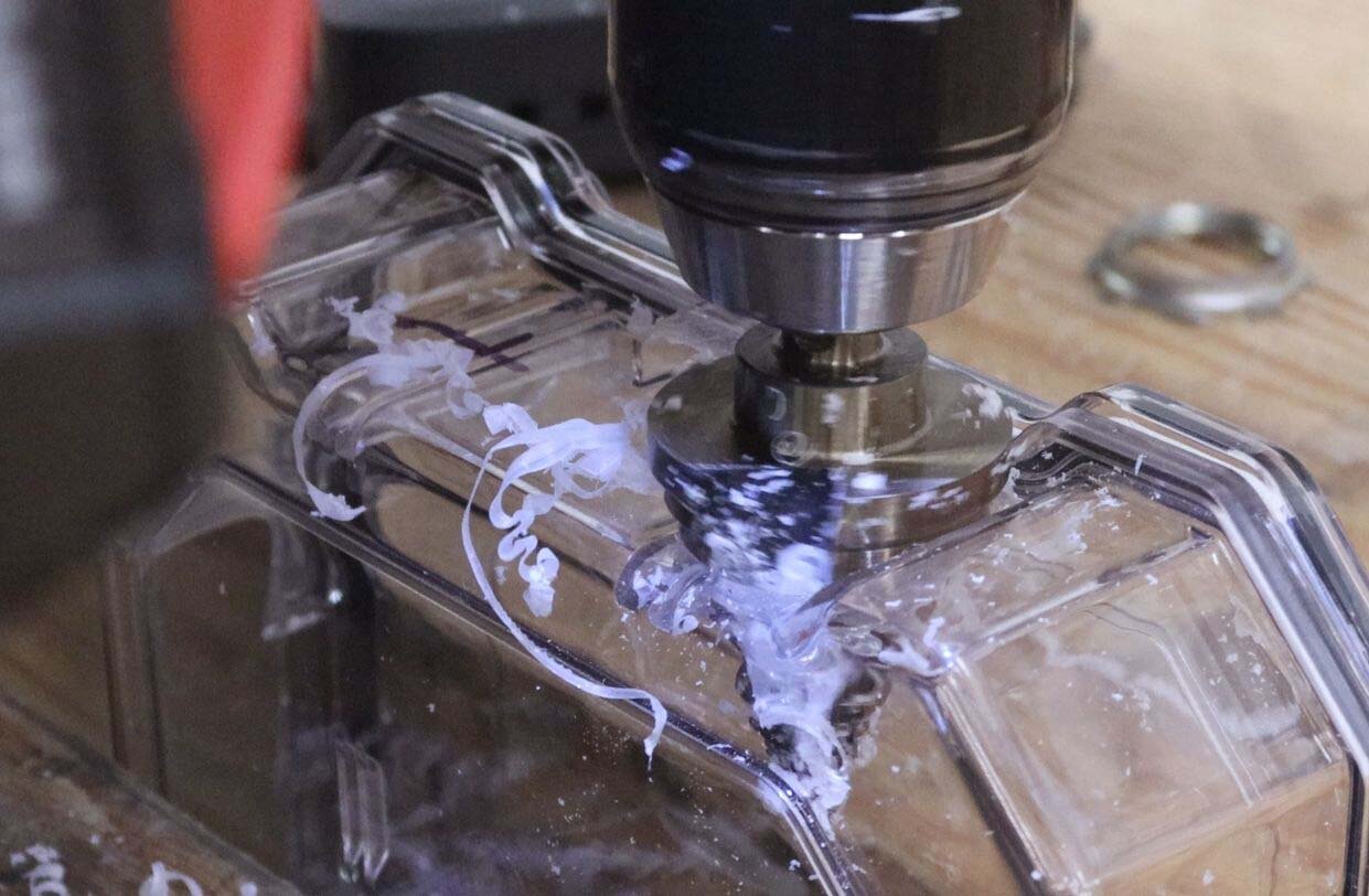
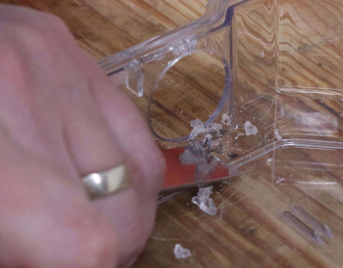
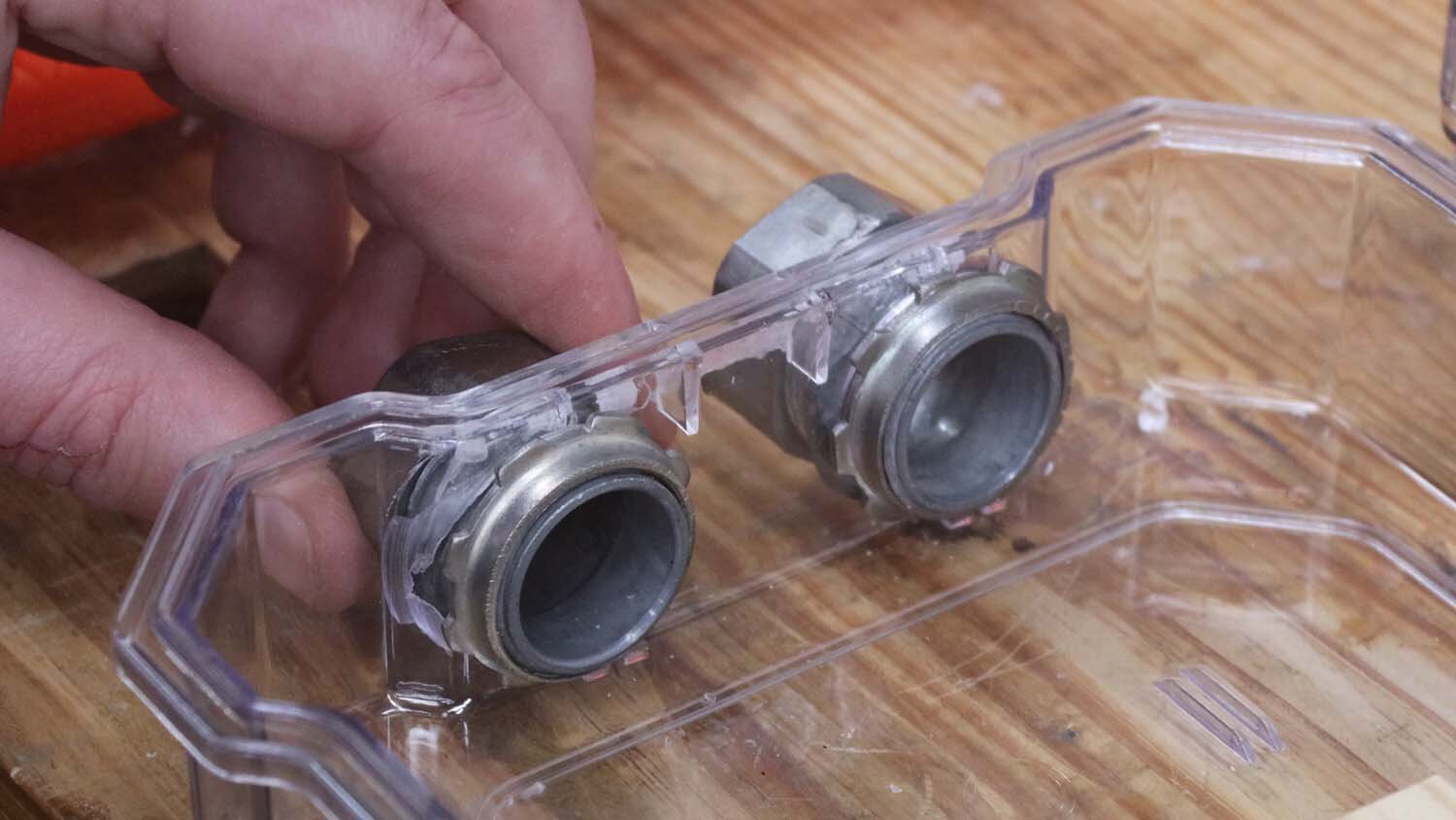
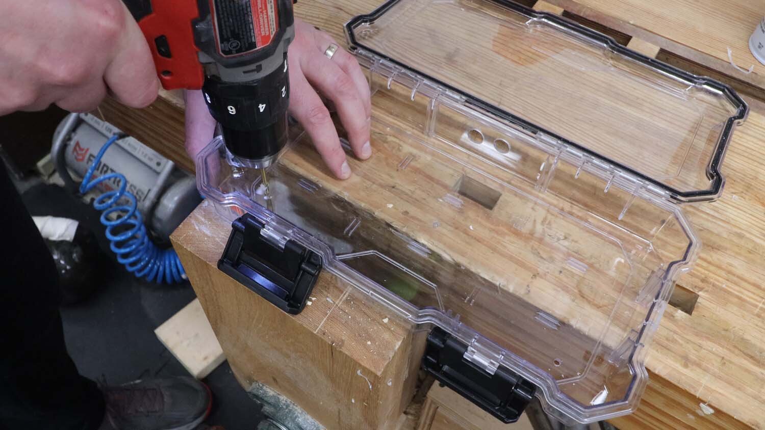
I'm going to route the current transformer wires through conduit, and since this plastic box isn't really meant for this purpose, I need to make some modifications. First off, I trim off any extraneous plastic bits with a chisel. Then I drill holes for the two conduit connectors with a step drill.
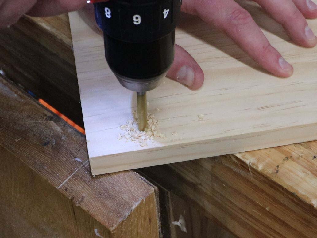
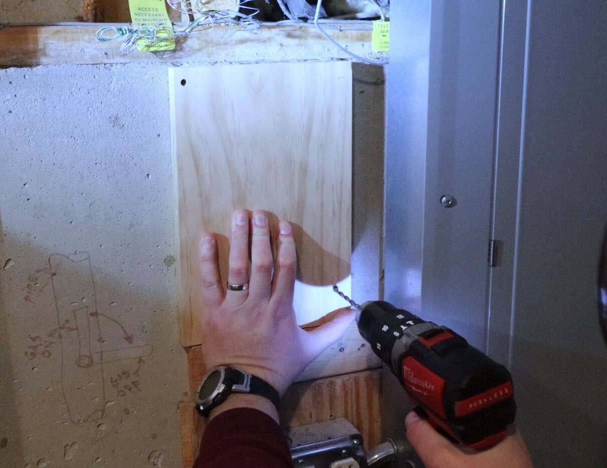
To mount the box to the wall, I affix a piece of wood to the concrete using some Tapcon screws.

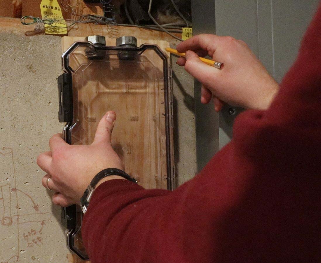
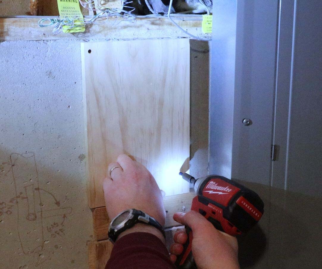
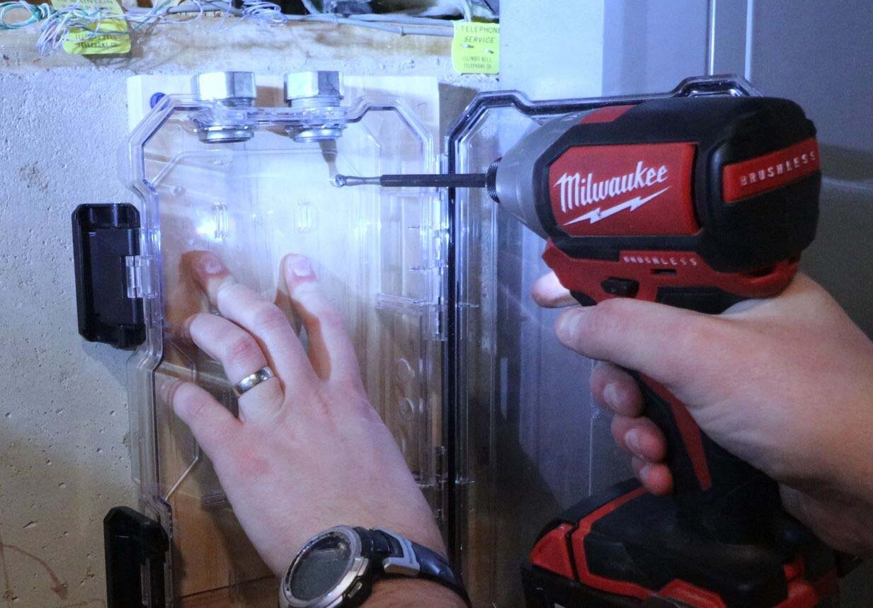
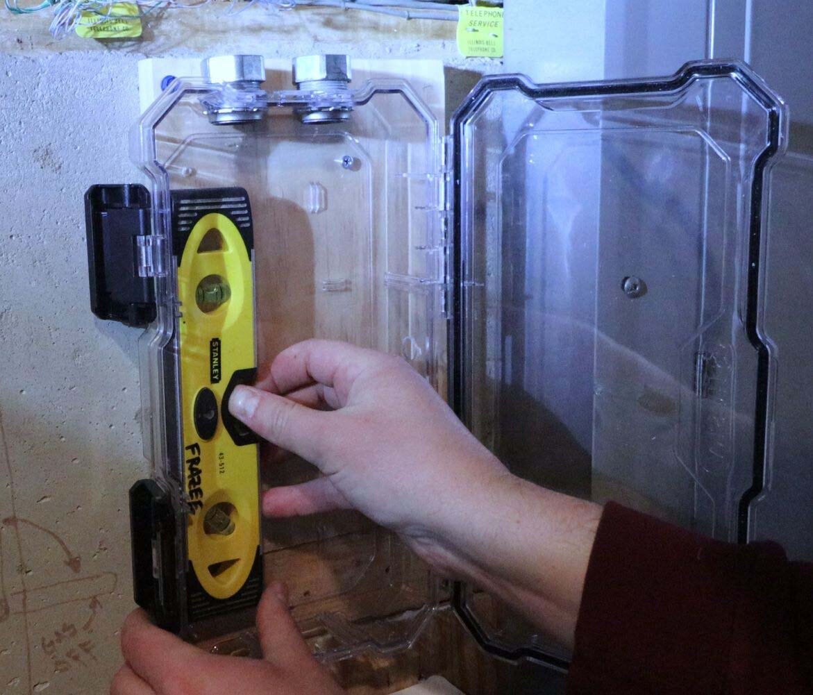
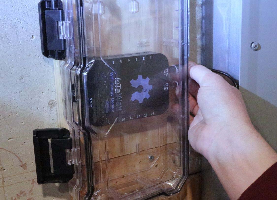
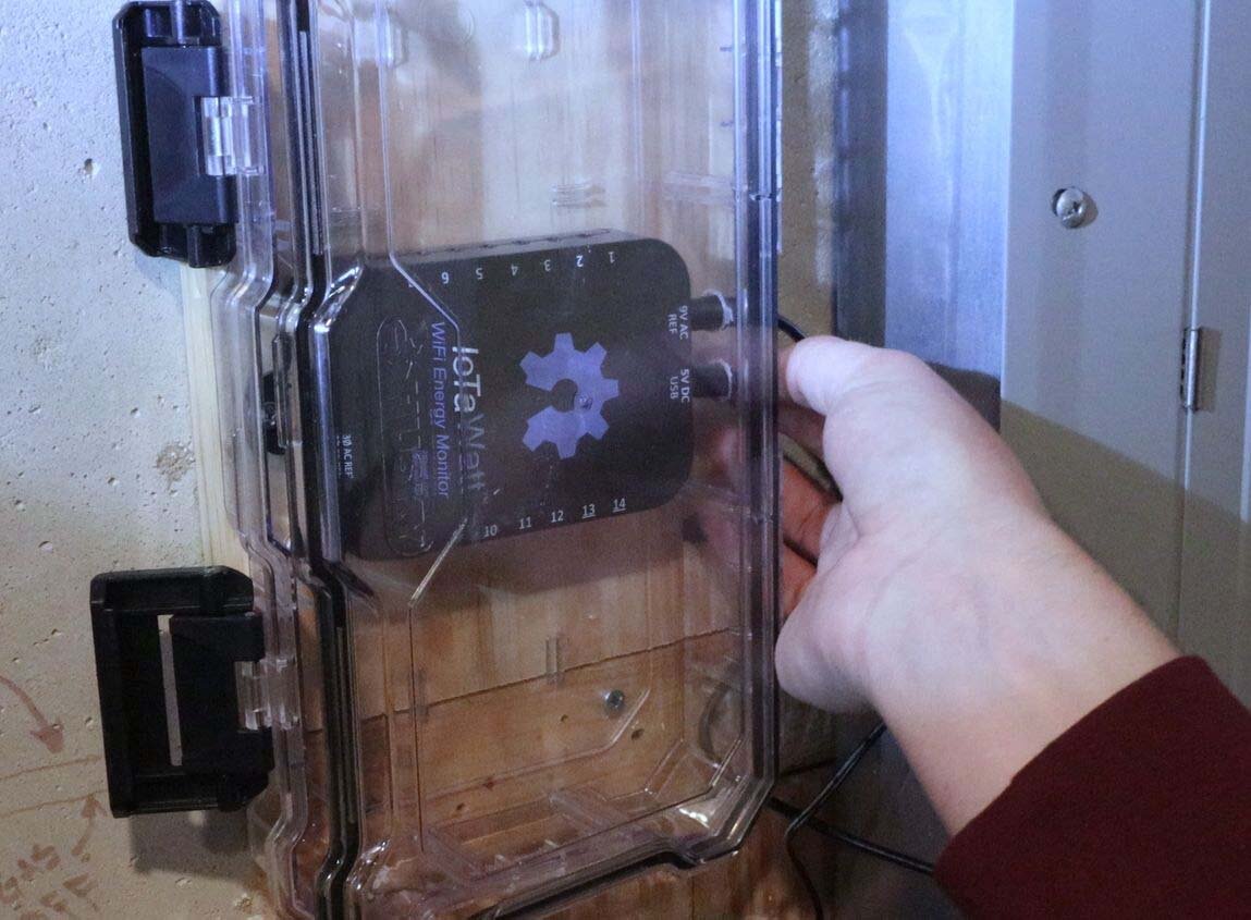
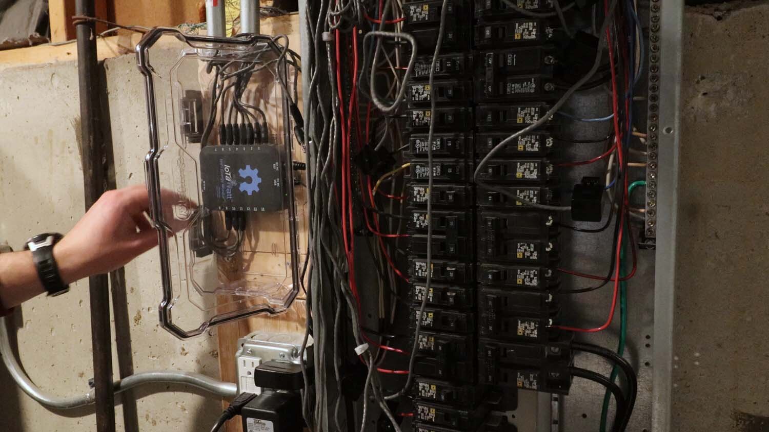
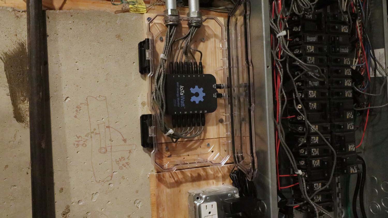
The plastic box is attached with four wood screws, and then two more screws holds the IoTaWatt in the box. With the IoTaWatt secured in the box, I hook up the 9V reference and the USB power supply.
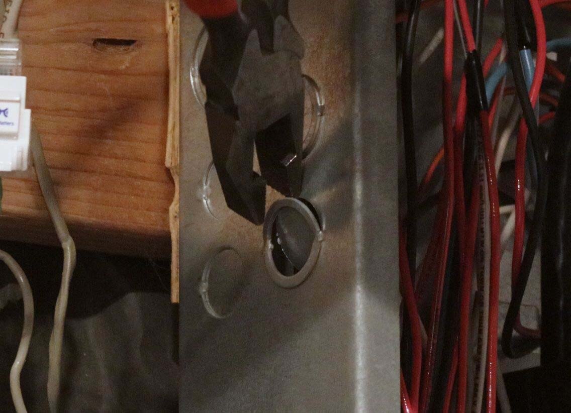
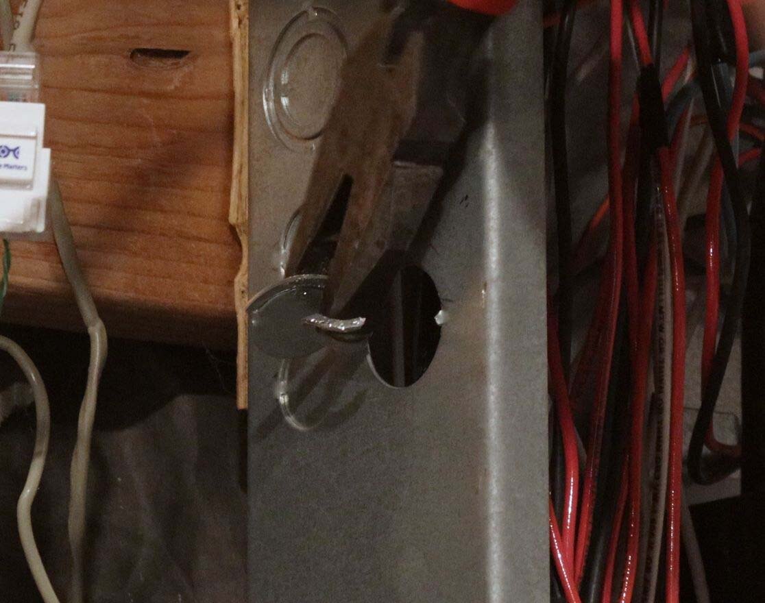
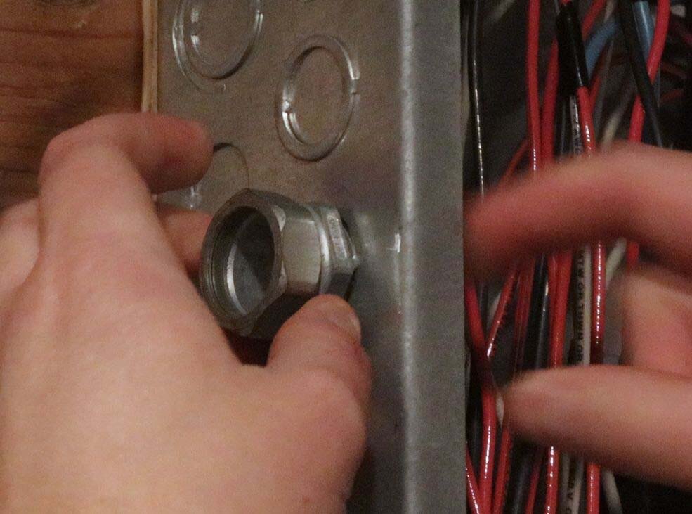
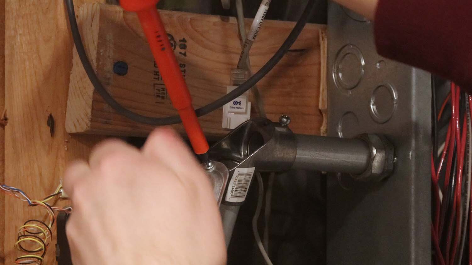
I'm running the current transformer cables to the IoTaWatt through two 3/4" conduits, so I remove two handy knockouts in the side of my electrical panel with a flathead screwdriver and pliers.
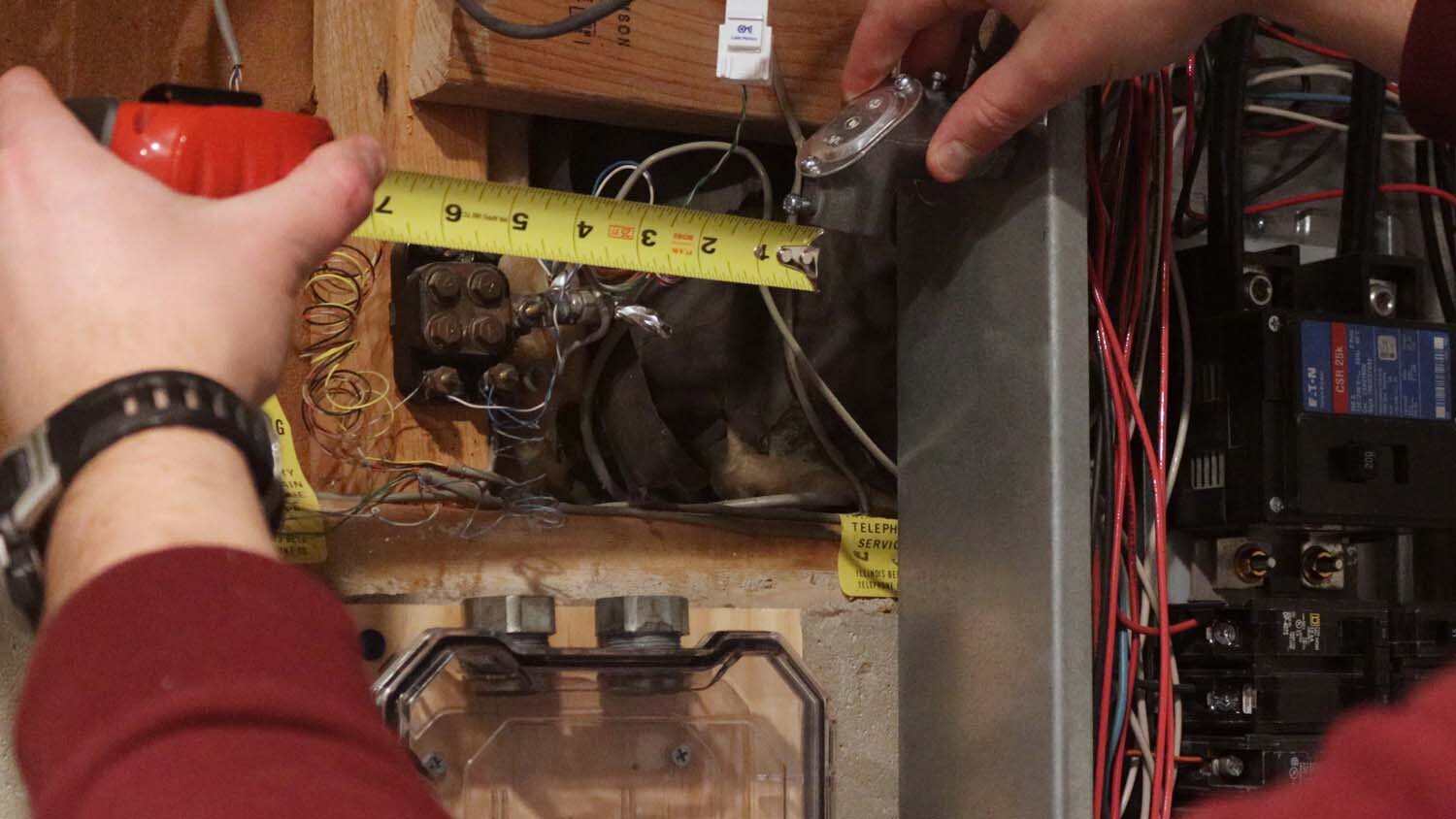
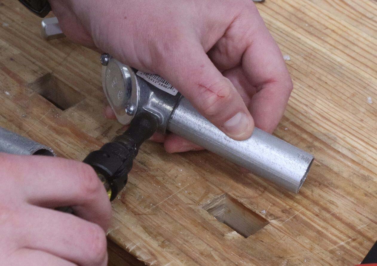
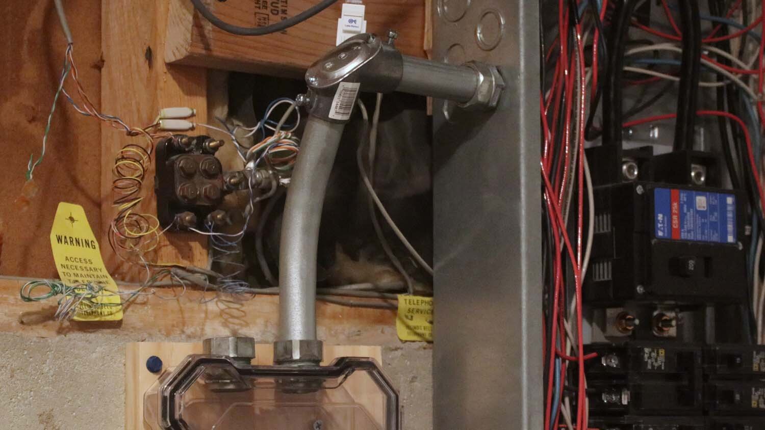
Your routing will likely differ from mine, so I won't go into much detail on the conduit measuring and bending. If you're fortunate enough that you can just use a couple of straight conduit nipples to connect between the panel and the plastic box, great. For mine, I did a couple short runs of conduit with a pull elbow at the corner.

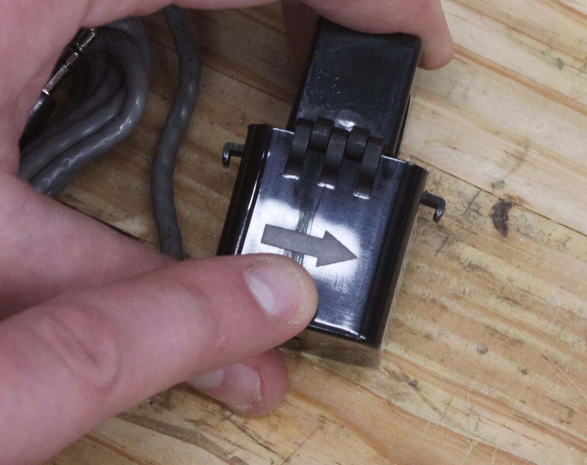
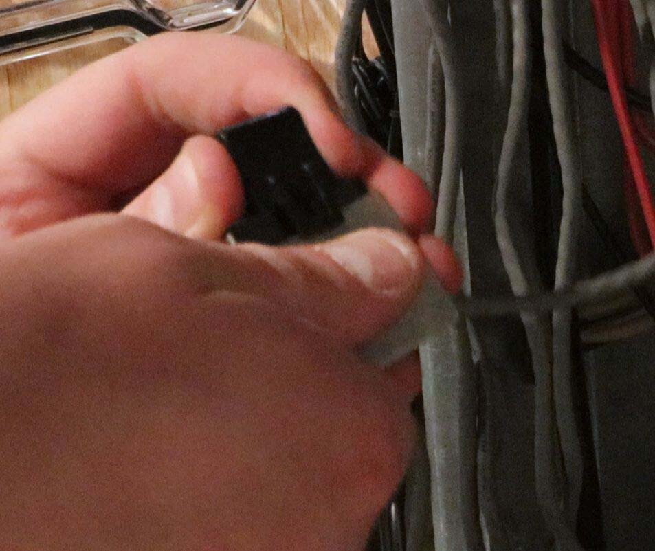
Notice that the current transformers have arrows stamped into the plastic, which indicates the orientation of the transformer with relation to the conductor. You can read more on this in the IoTaWatt documentation. If you end up installing one backwards, it's not a big deal because you can "fix" it in the software setup later on.
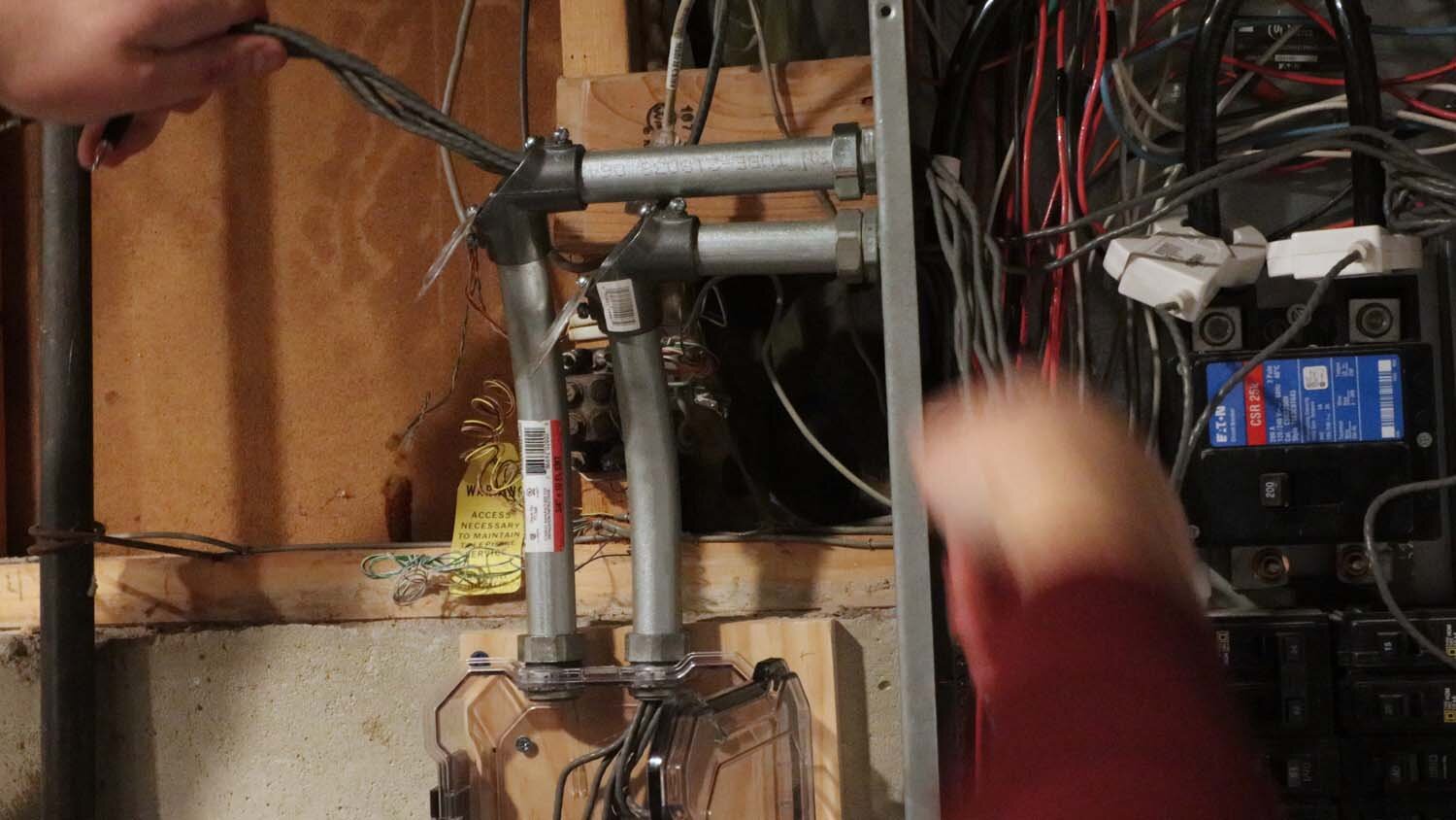
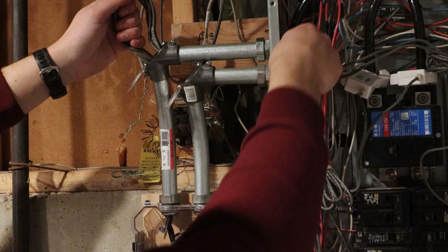
With the conduit hooked up, I fed the current transformer wires through the conduit, with seven wires per conduit. If you're patient, you can squeeze all 14 wires through one 3/4" conduit, but it's basically impossible to switch one out later on if it stops working. Therefore, I don't recommend only one conduit for this.
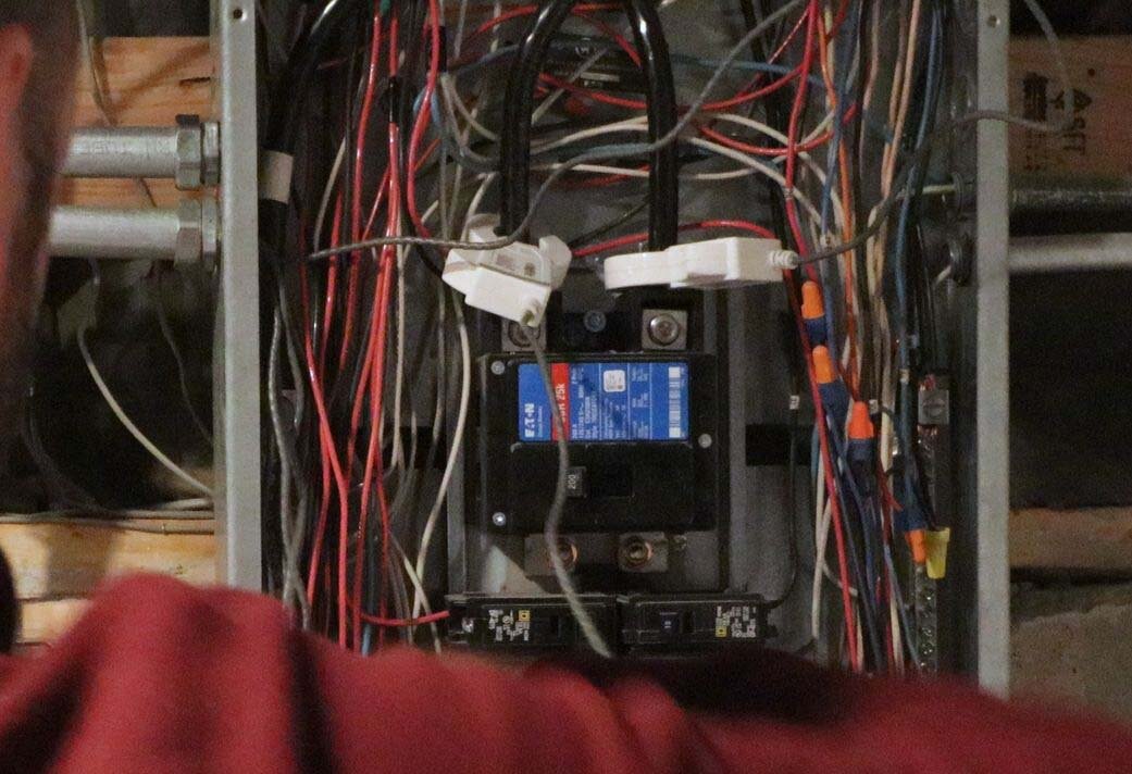
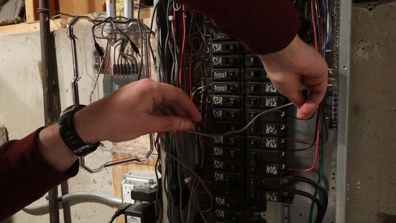
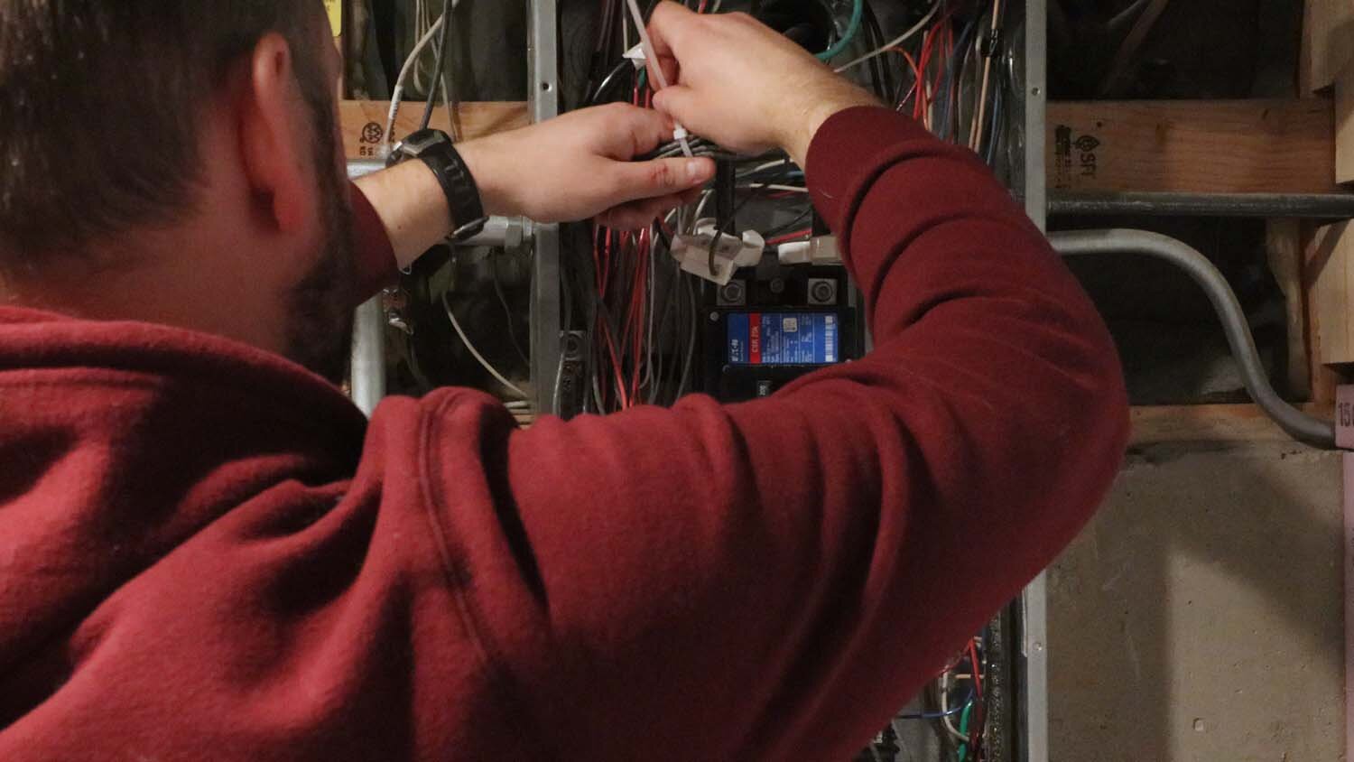
Start with the two current transformers for the mains power (the big wires coming from your meter). These should go into Inputs 1 and 2 of the IoTaWatt, and the current transformers just clamp around the power cables. After that, it's a simple matter of hooking up the remaining current transformers to the circuits you want measured, being sure to note which correlates to which Input on the IoTaWatt.
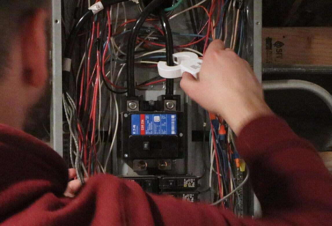
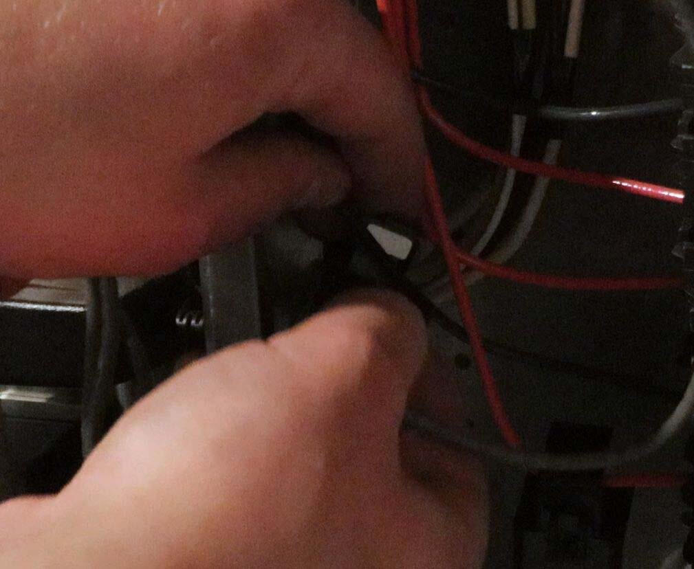
You might find it helpful to pry open the current transformers with a putty knife or flathead screwdriver, but be careful not to break the plastic tab.
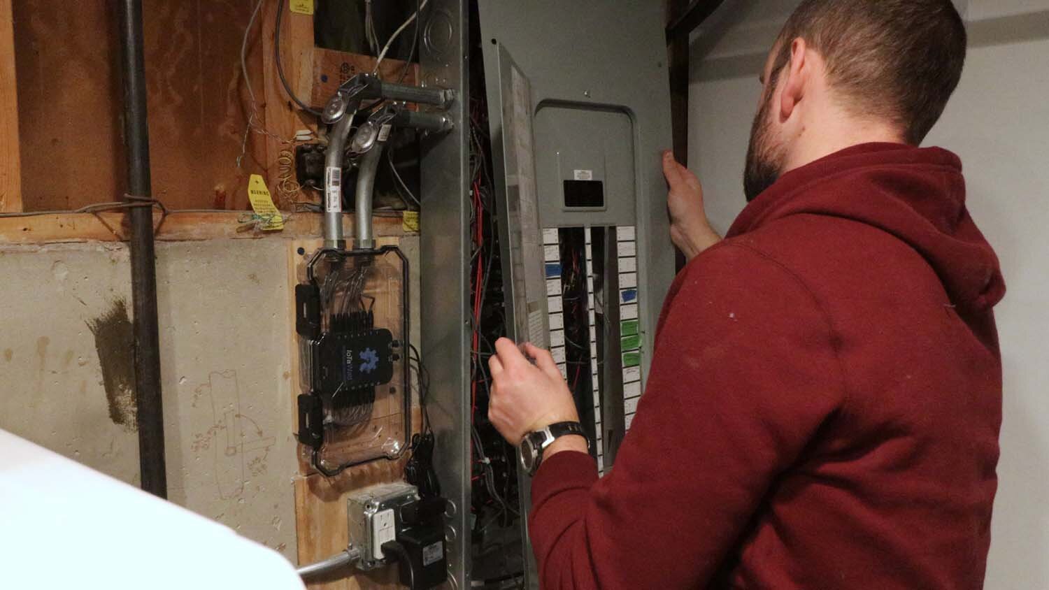
After installing all of the current transformers, it's a good idea to neaten everything up with zip ties. Then put your panel cover back on, and all should be done with the physical installation!
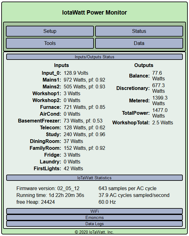
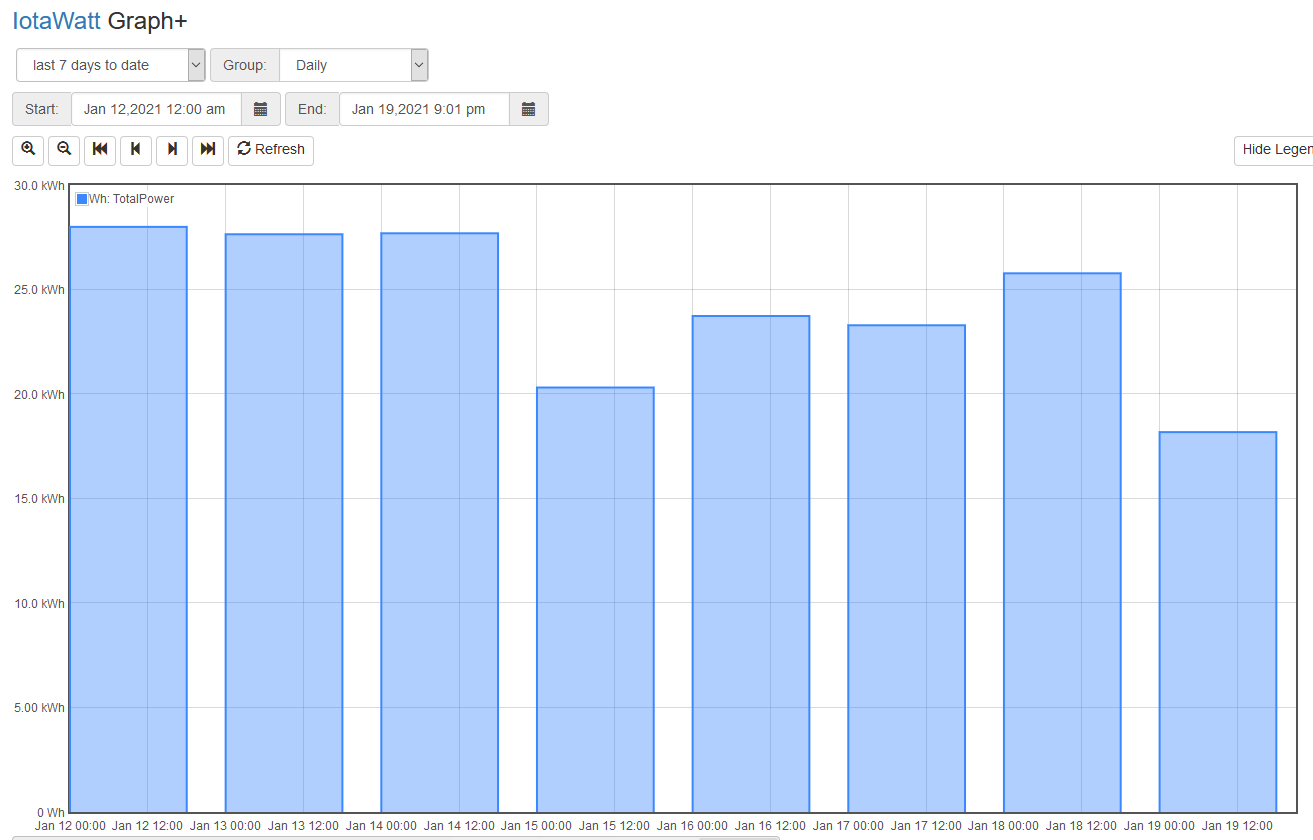
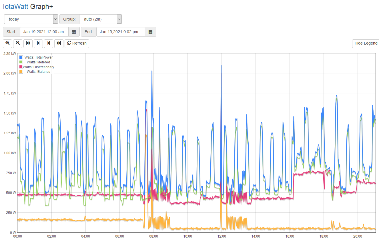
The software installation of the IoTaWatt is well-documented on their website, so I won't go through the details in that. I will note that I found it to be relatively straightforward, and the data that I'm getting from the IoTaWatt is very enlightening.
I hope this was instructive, and thanks for viewing!
If you enjoyed this article, subscribe to my YouTube channel for more!
—————————————————————————————
Below is a listing of the supplies you will need.