
Installing a Router Lift in a Table Saw Extension
In this article, I'll be installing a Jess-Em Rout-R-Lift II in my table saw extension. I have a bad habit of leaving projects undone (in this instance, since Christmas 2019), so I thought I'd take the time to install this over the weekend. Jess-Em makes tables specific to their router lifts, but it's fairly straightforward to install them in your own table.
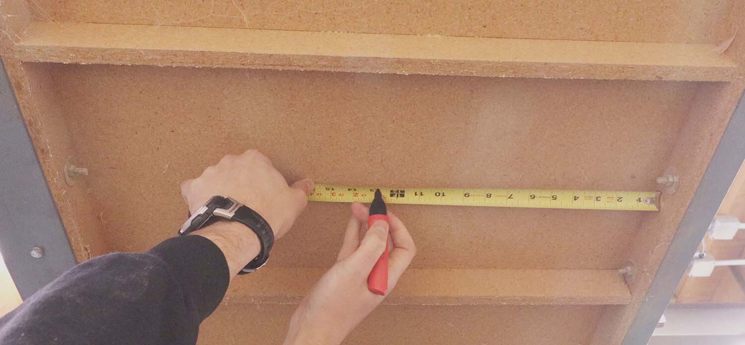
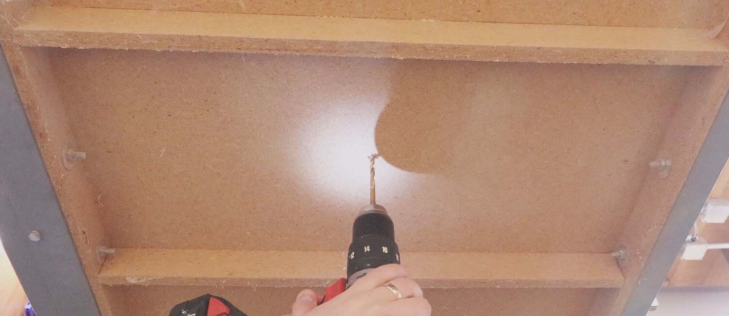
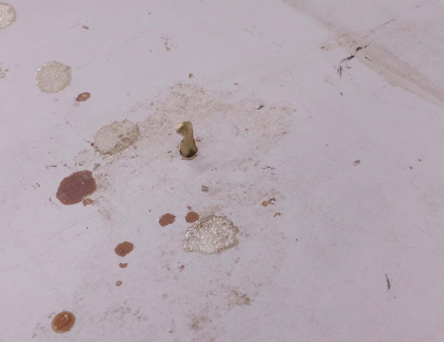
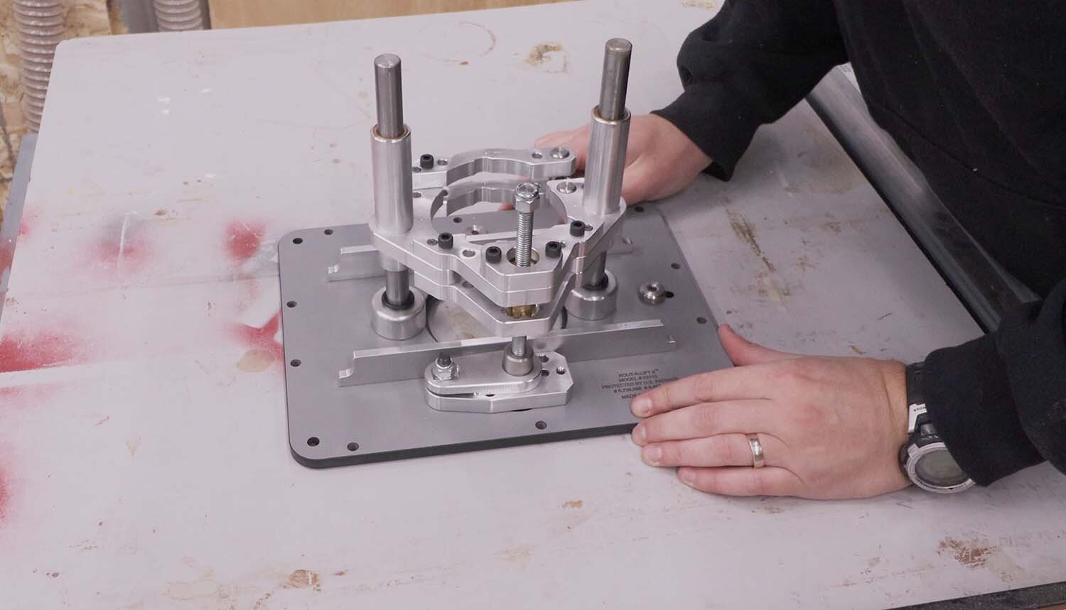
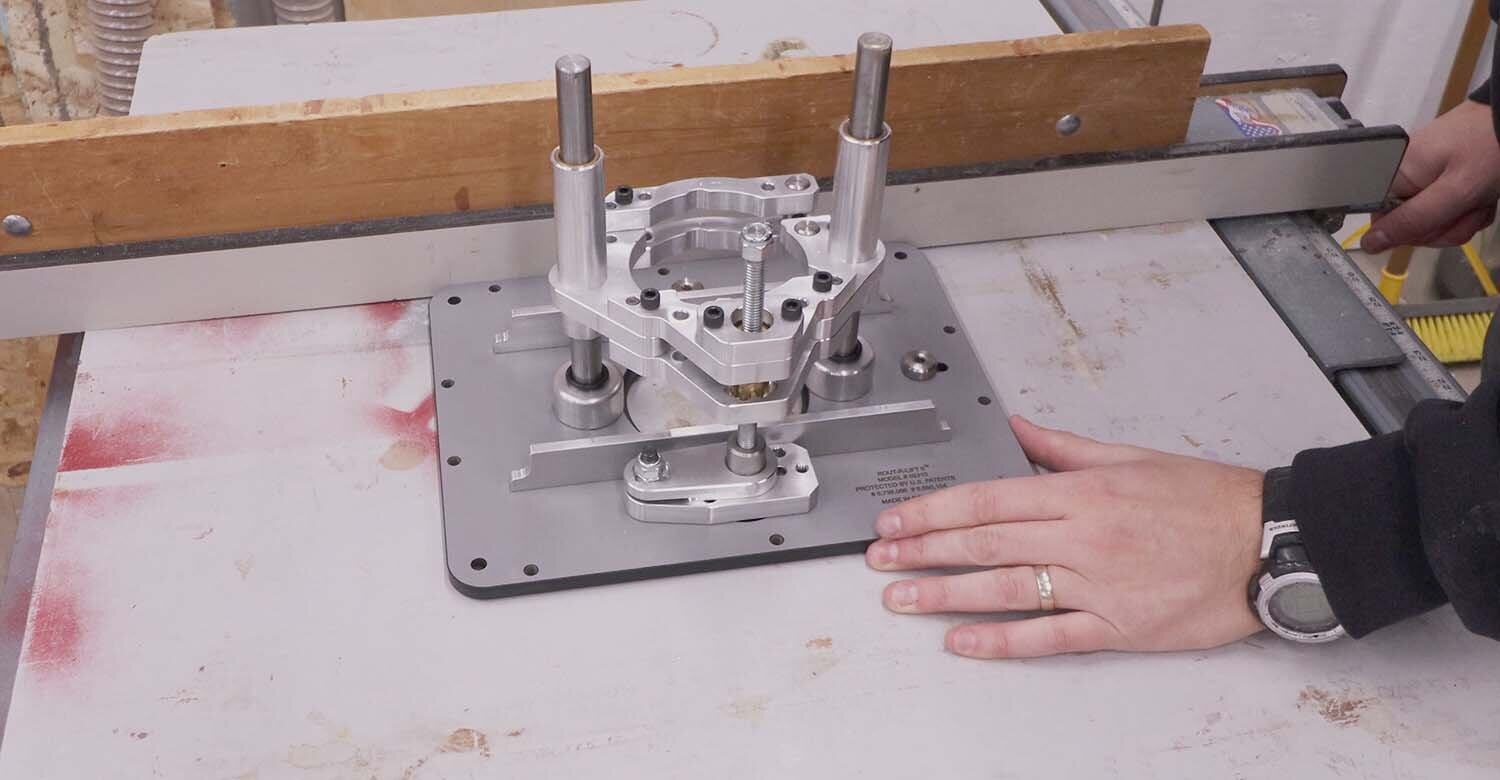
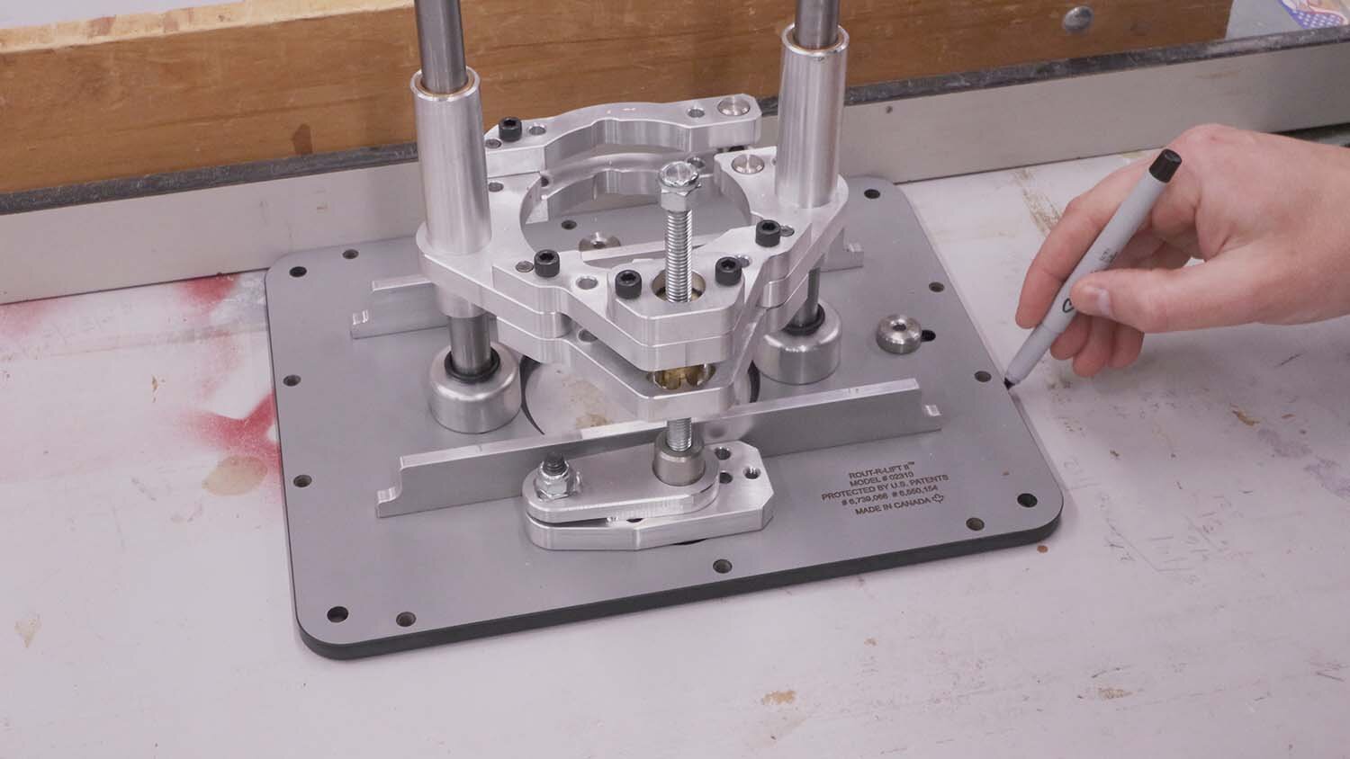
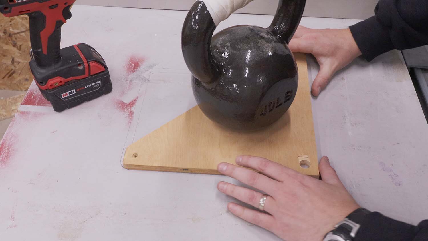
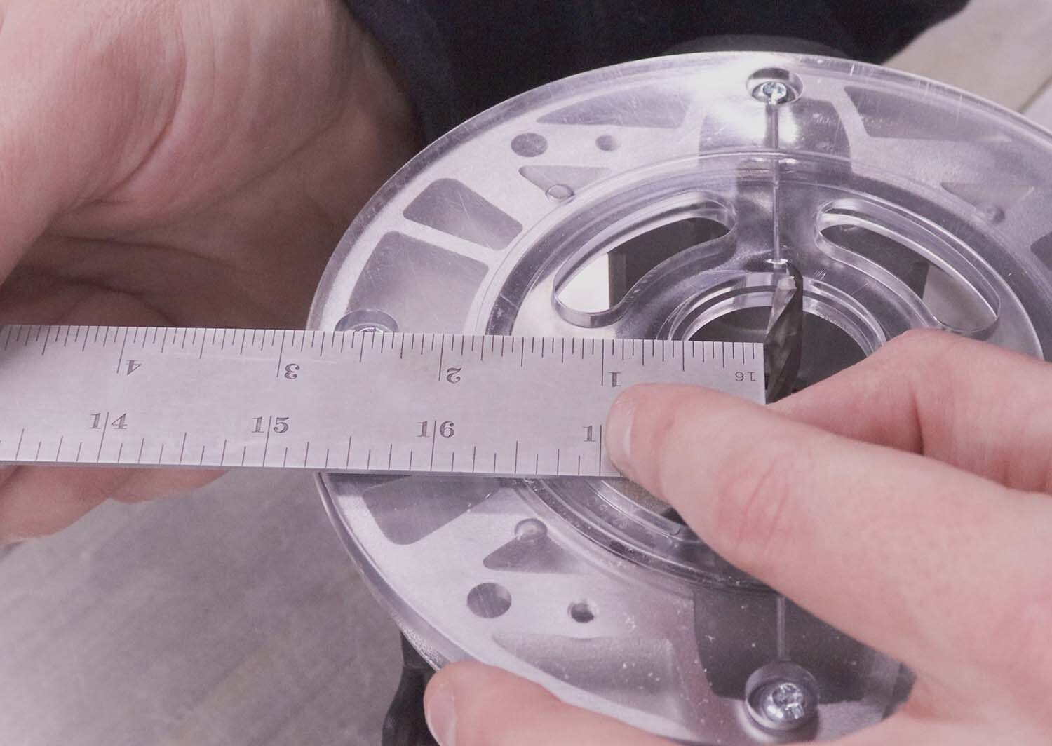
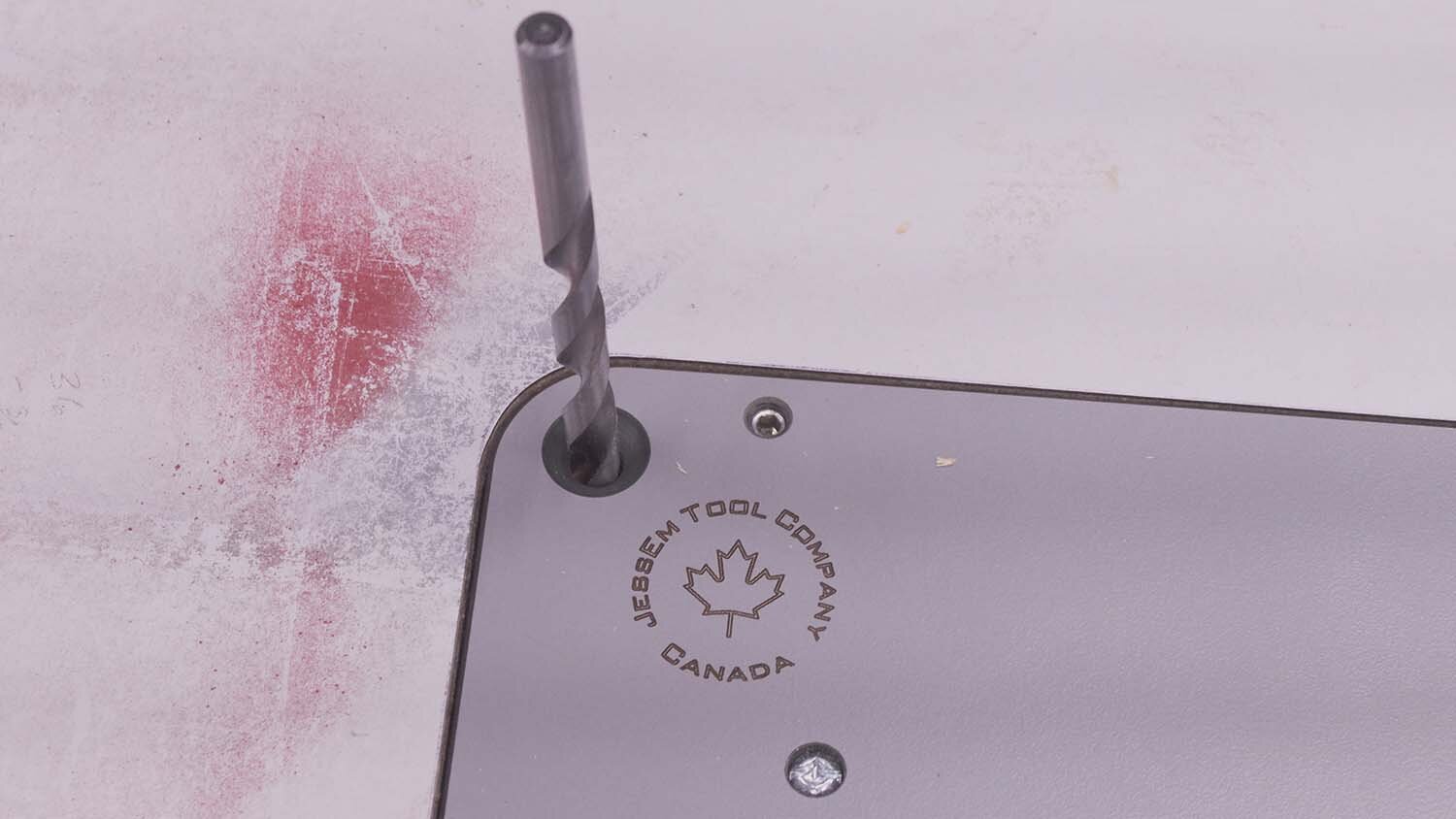
My dad built this table saw extension years ago, and it’s simple MDF overlaid with a melamine top, reinforced with ribs every foot or so. I first start by finding the center of the table saw extension between two of the ribs, marking, and drilling a locating hole through the table. Using the hole, I center the router lift on the table, then use the table saw fence to square the router lift insert to the table saw. This isn't strictly necessary, but it does make all the other steps much easier. I then mark the outline of the insert plate with a fine permanent marker.
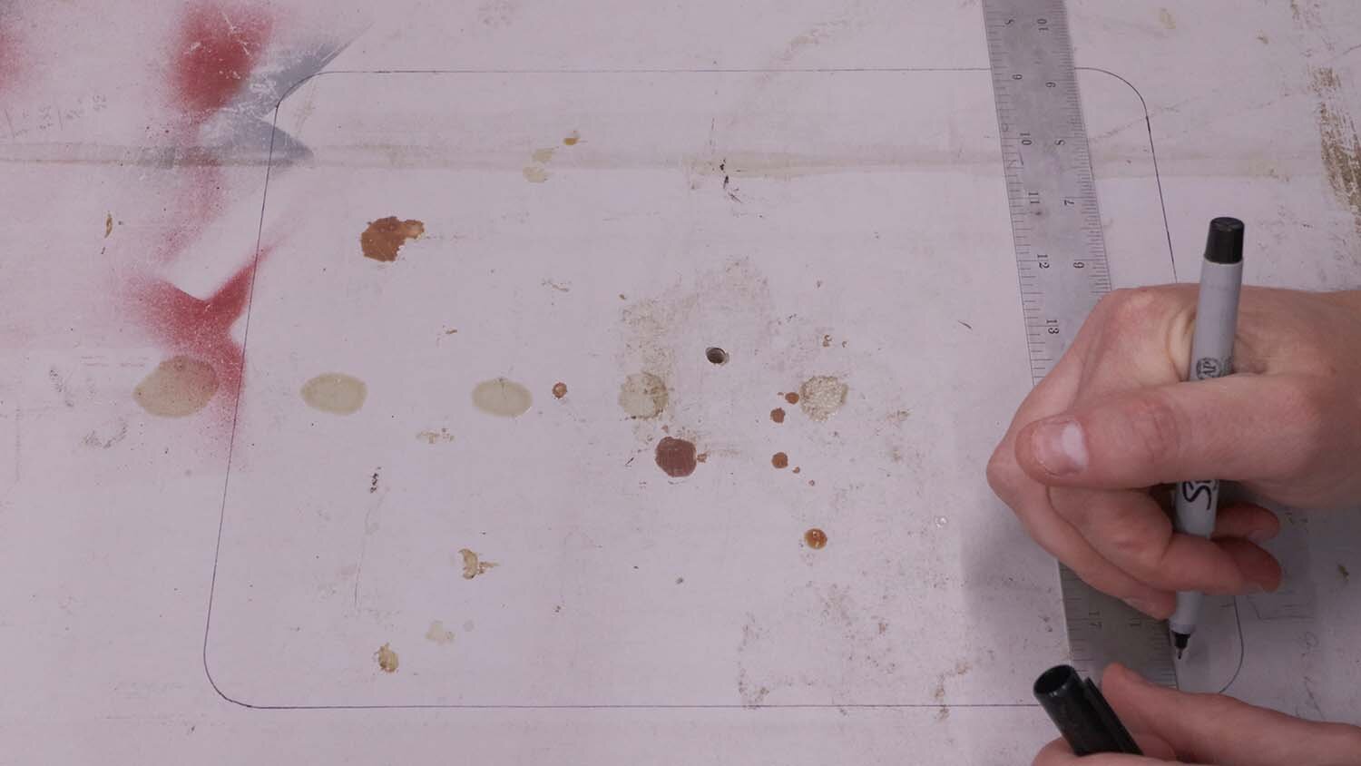
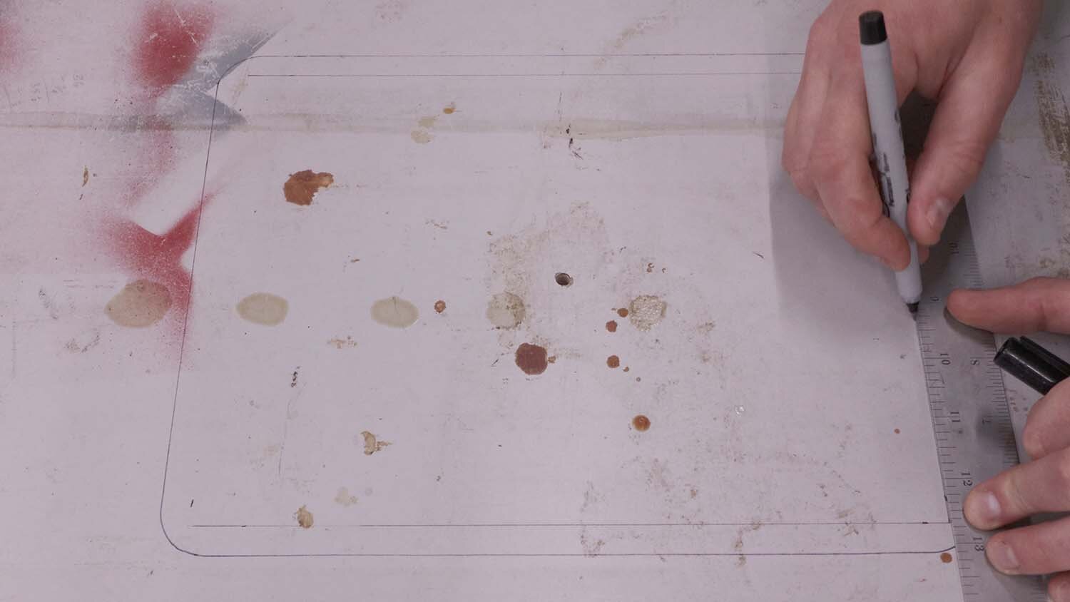
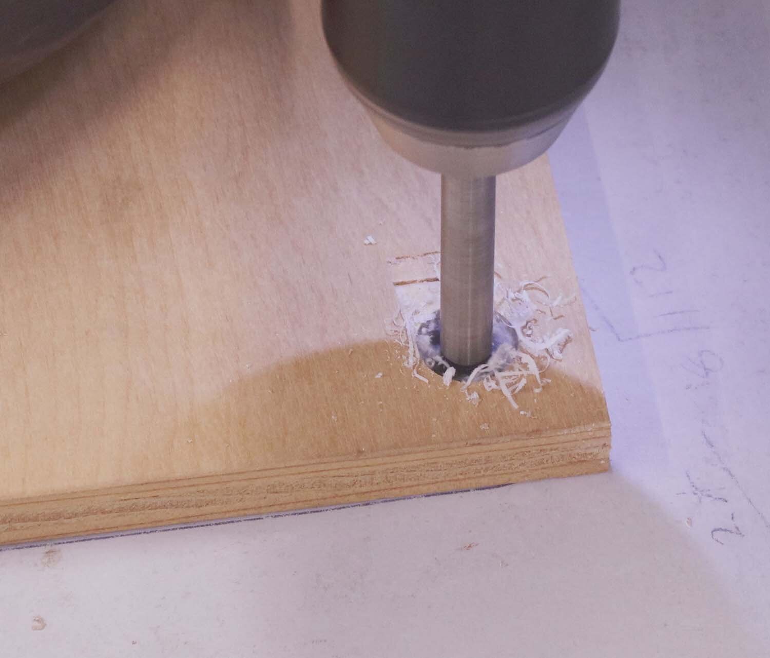
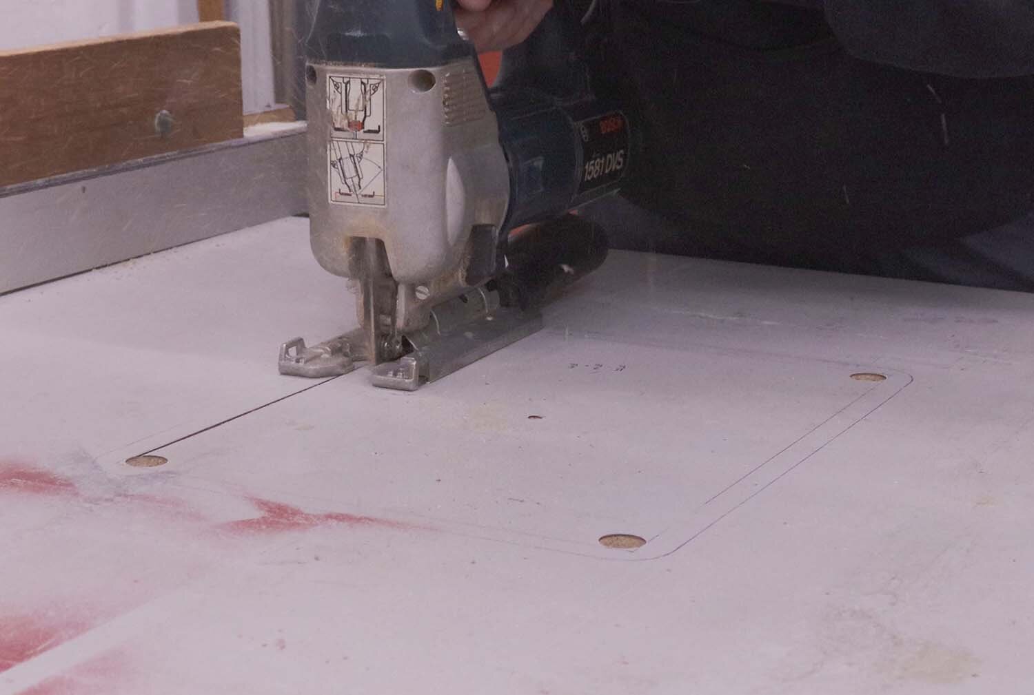
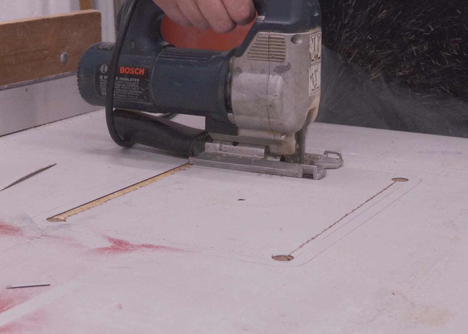
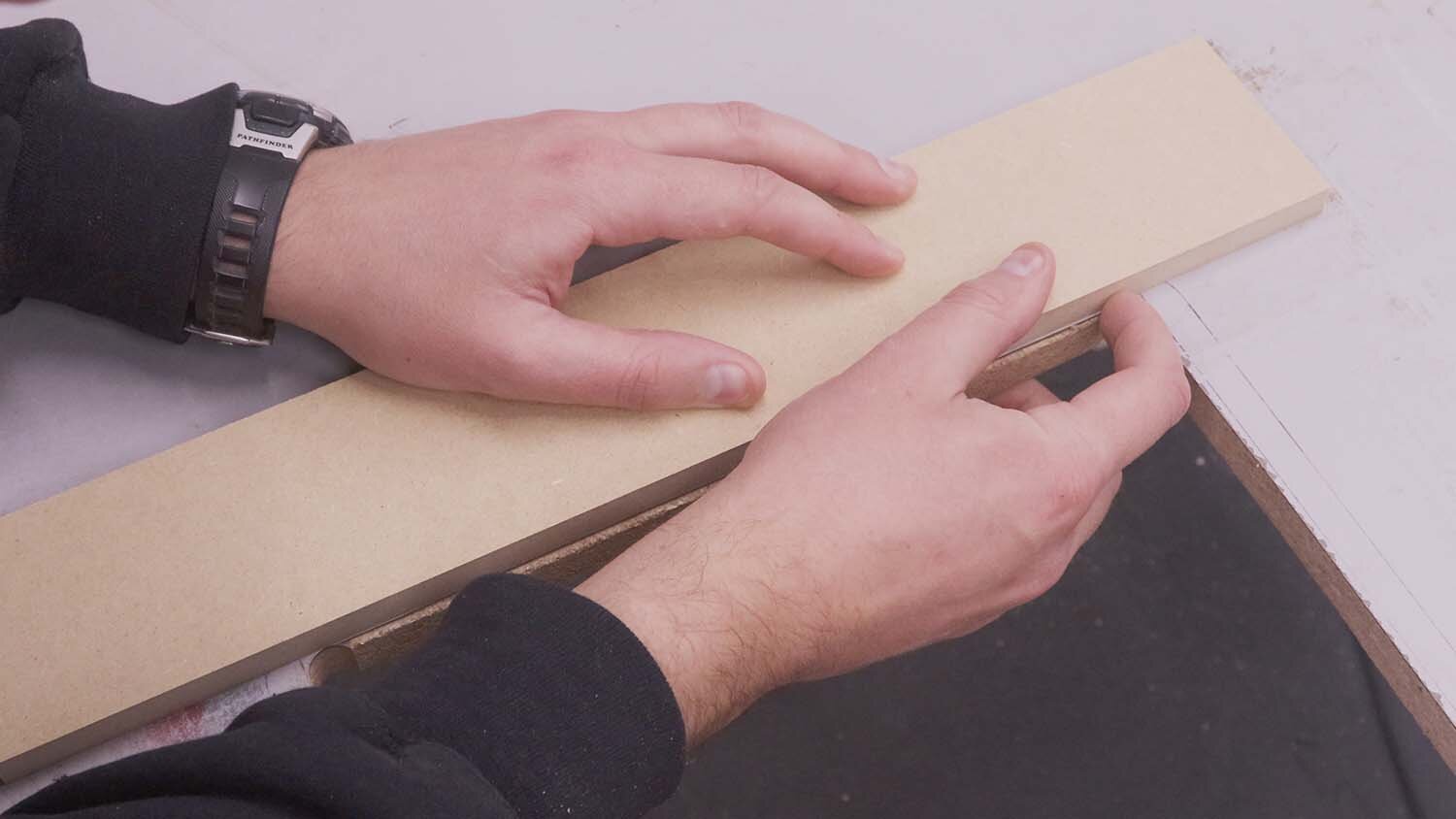
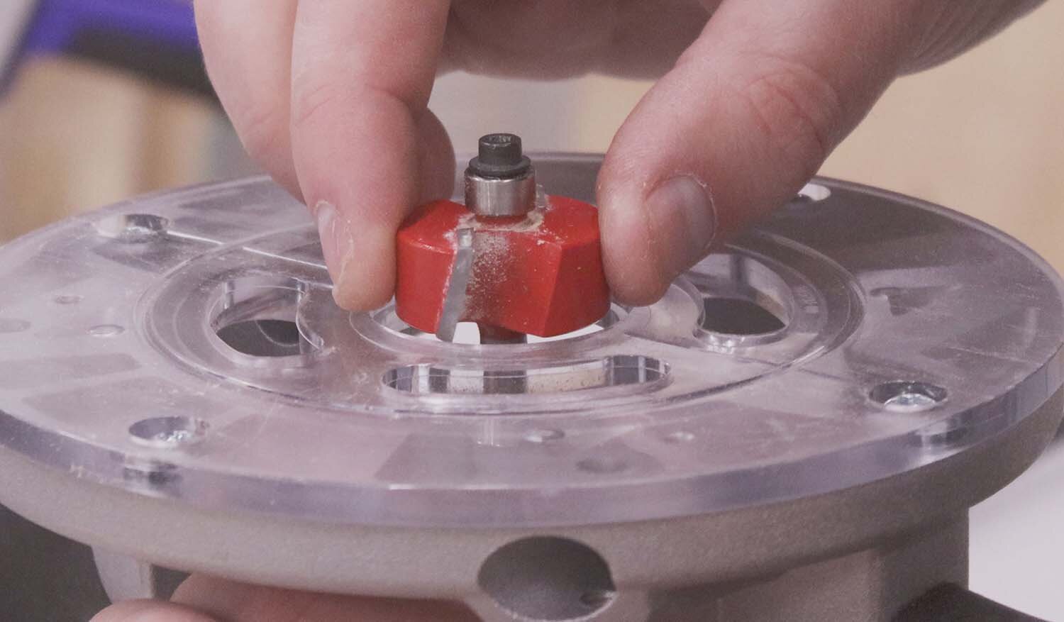
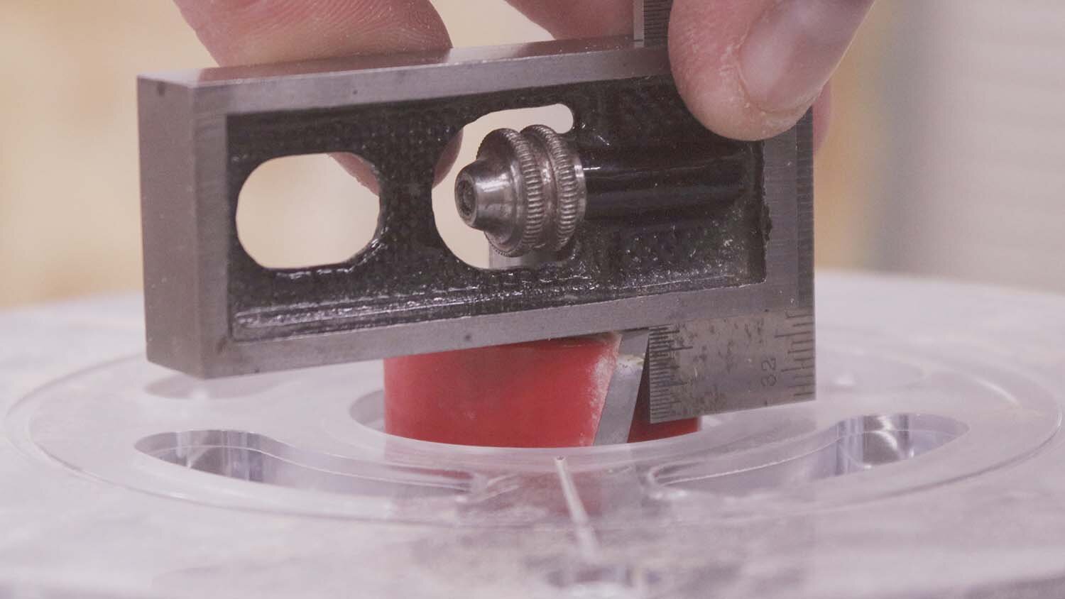
I'll be using a rabbeting bit to route a recess for the insert, so I need to mark for the outline that the bit's pattern bearing will follow. This takes a bit of math and depends on the specific rabbeting bit you’re using, but you want to offset the opening cut lines from the outside of the insert plate by the cut width of your rabbeting bit. Since the corners of the insert are rounded, I drill holes with this jig for the recess. I then use a jigsaw to cut out most of the waste.
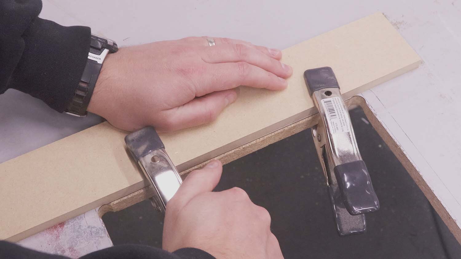
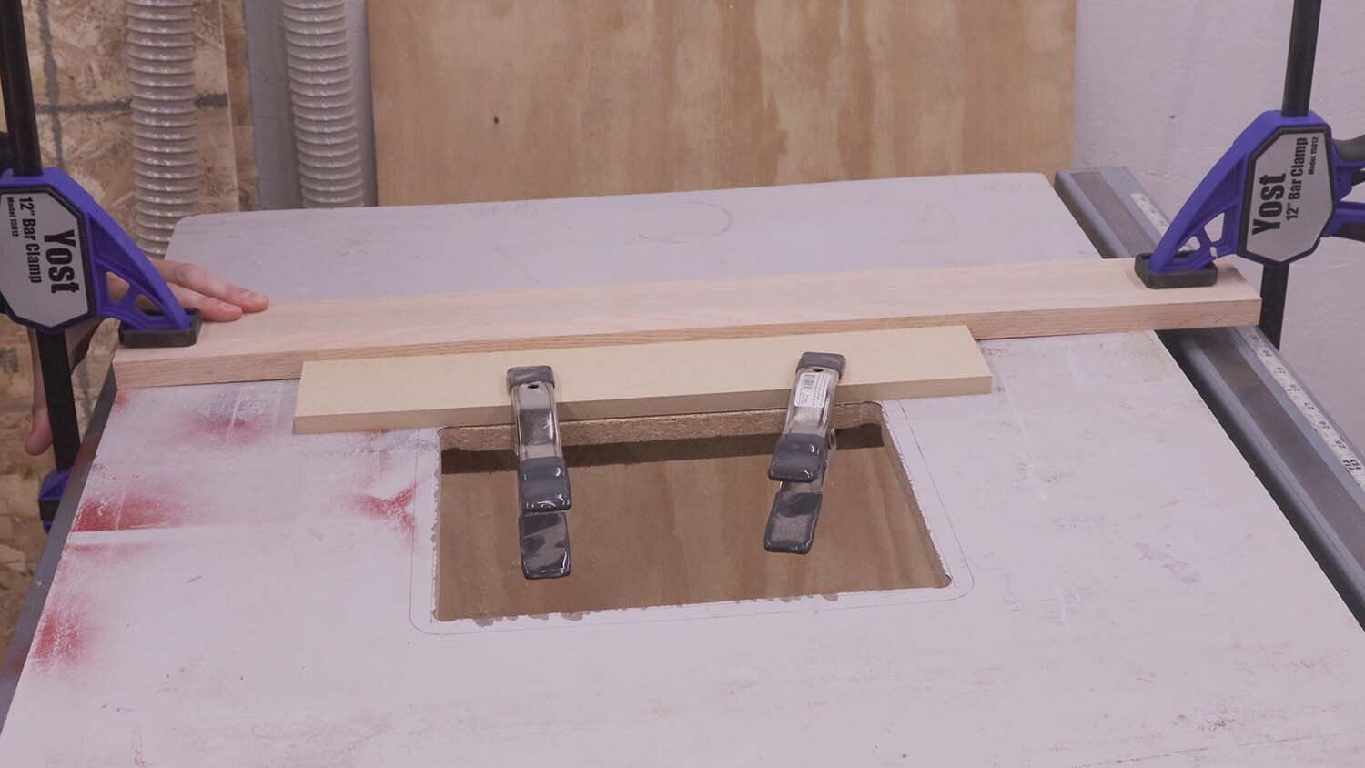
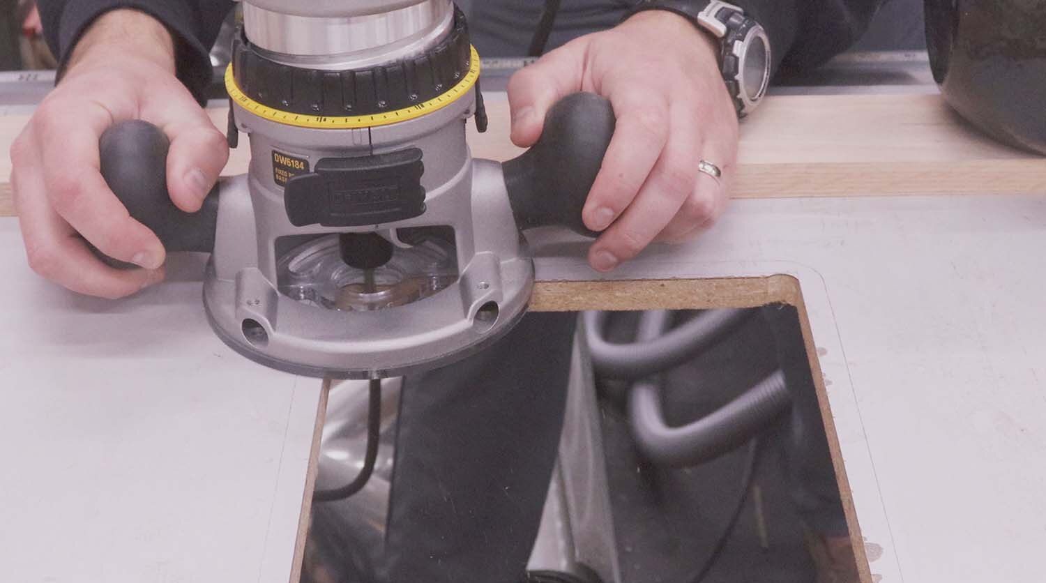
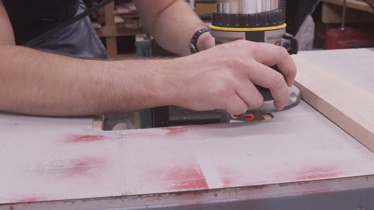
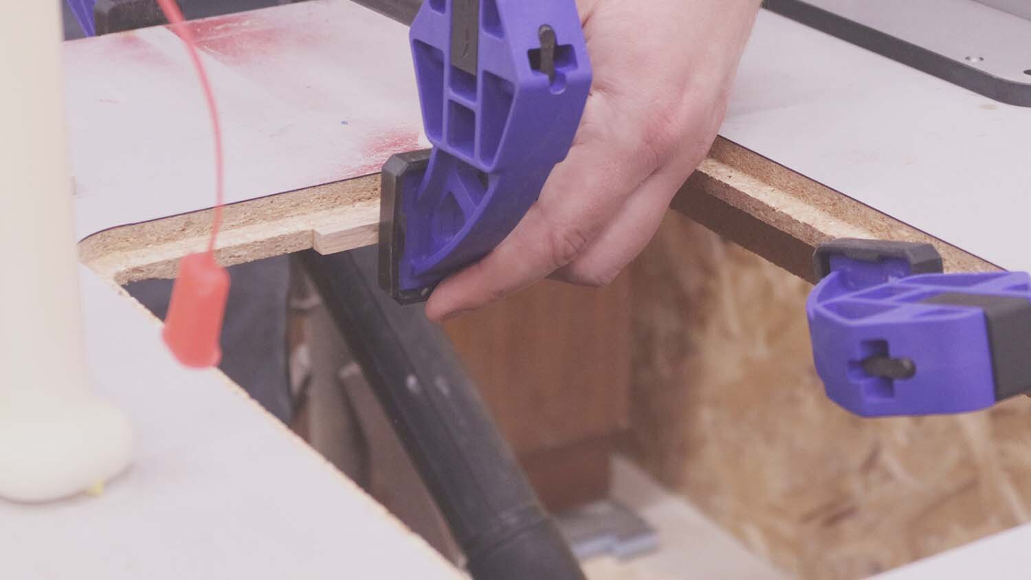
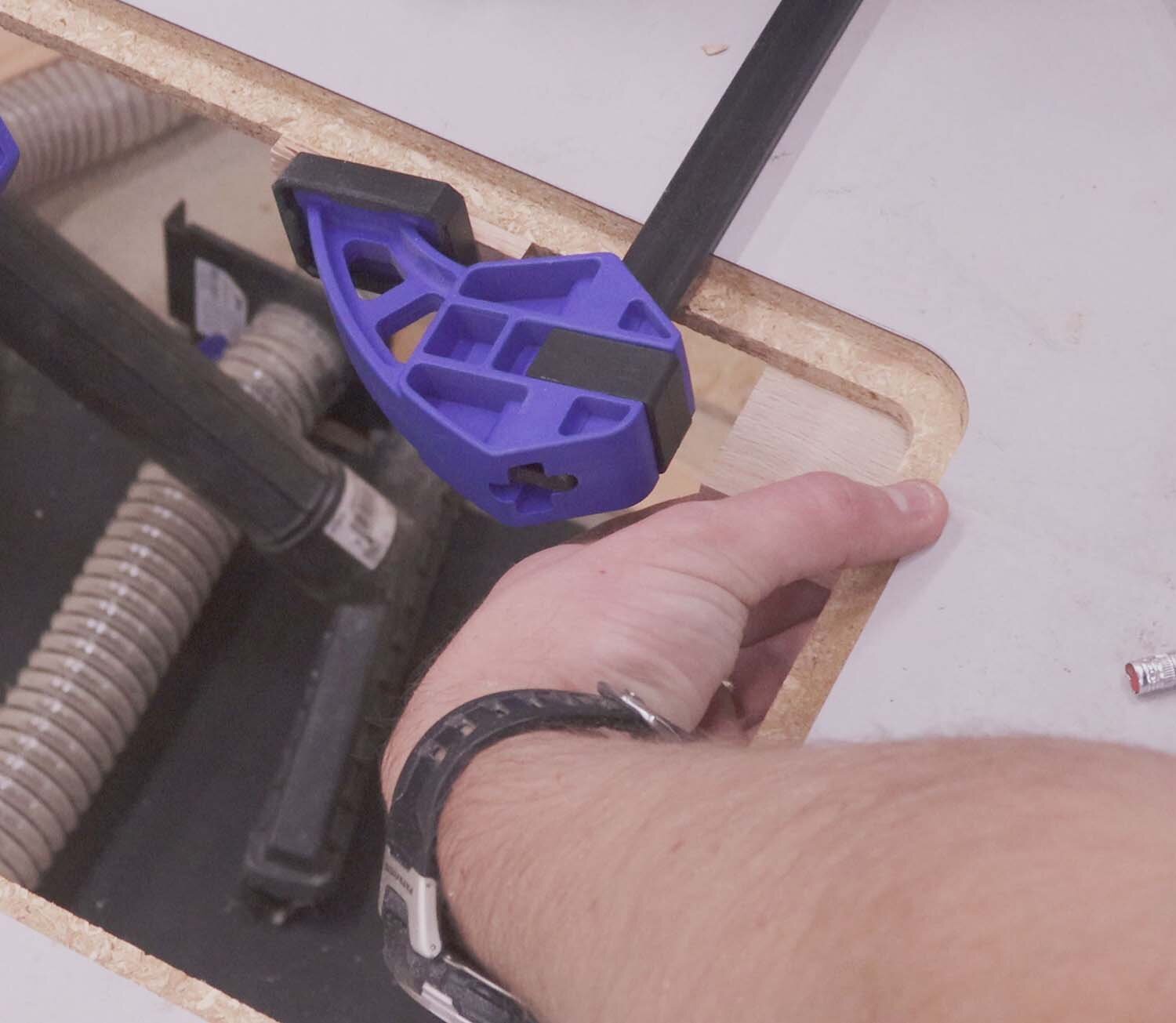
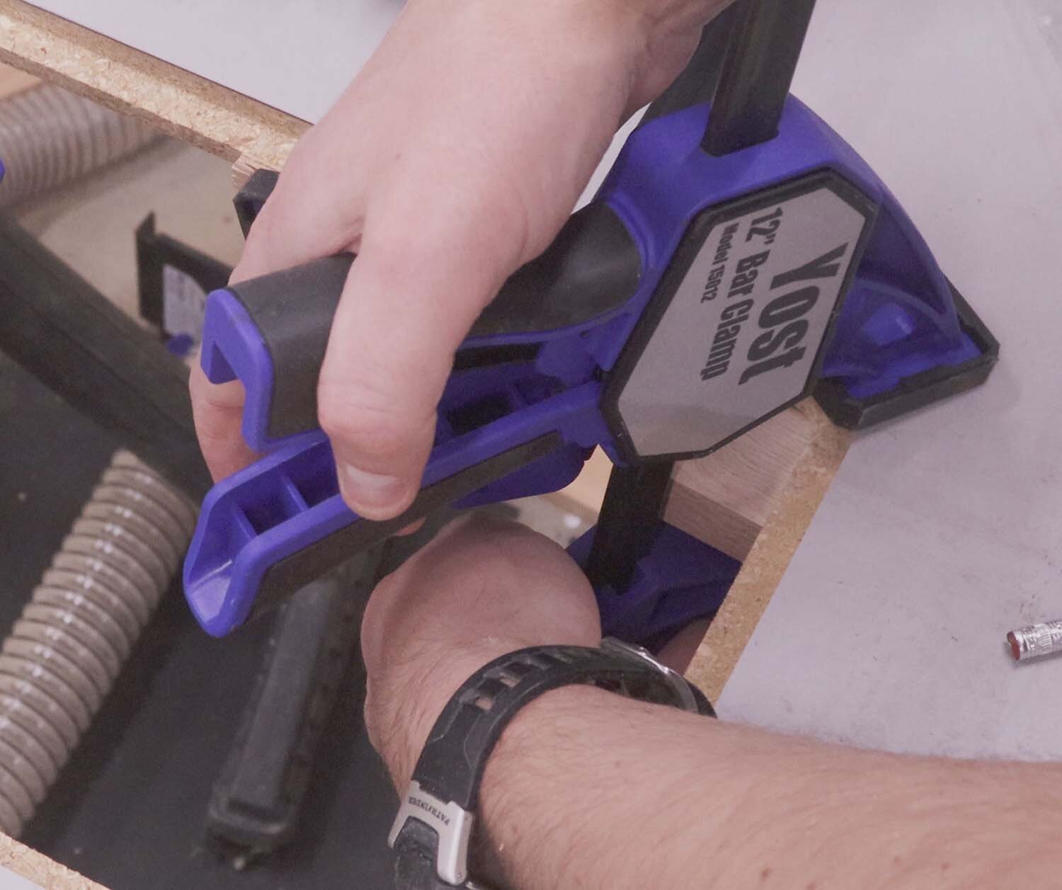
I'll use this straight bit to cut the sides of the recess to their final dimensions. For a consistent cut, I'm making a spacer of the same width as the distance from the router sole to the bit's cutting edge. I align this spacer with the corner holes I previously drilled, and then clamp the spacer so it doesn’t move. I then clamp a straight board against the spacer, which the router will follow.
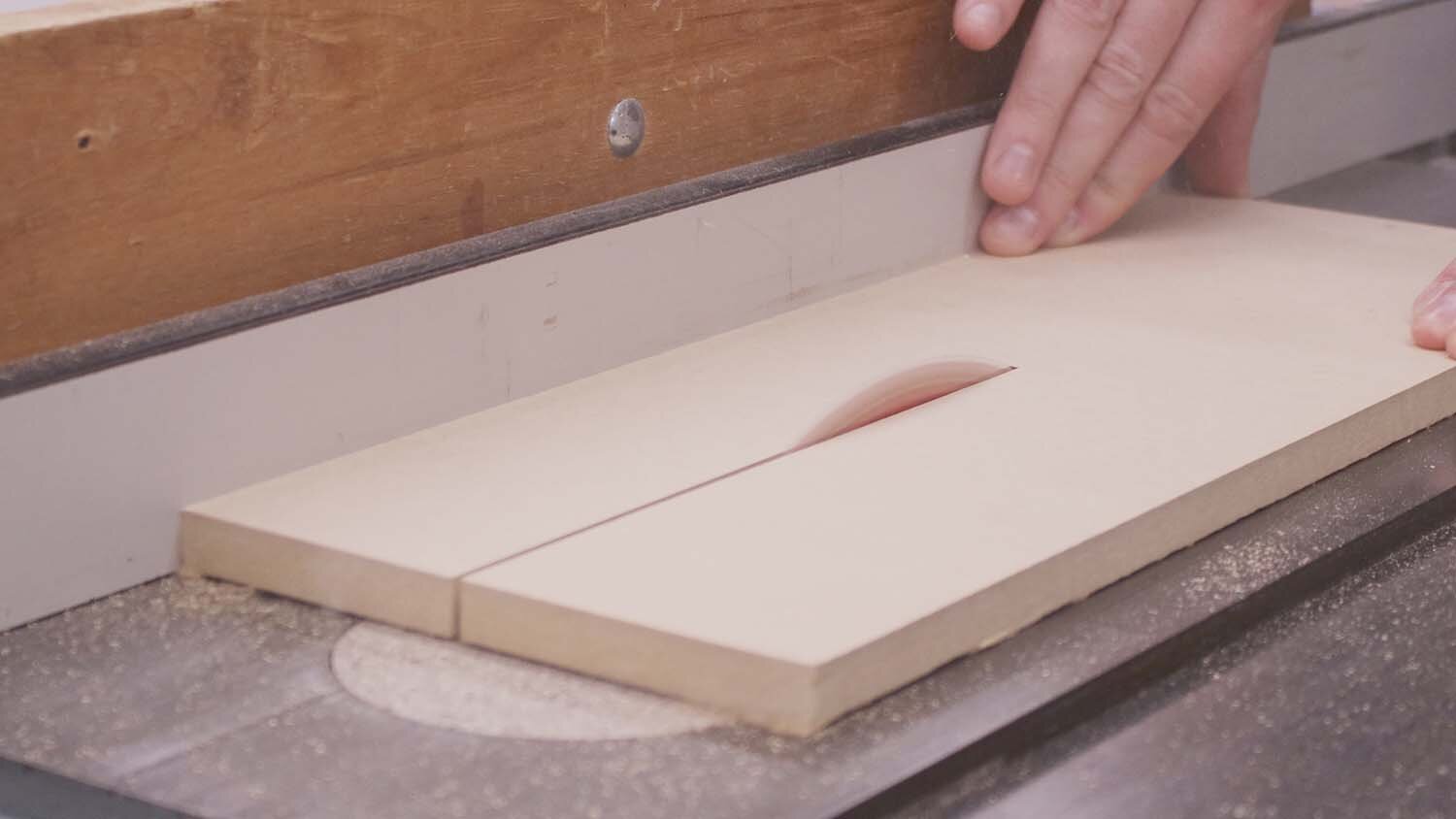
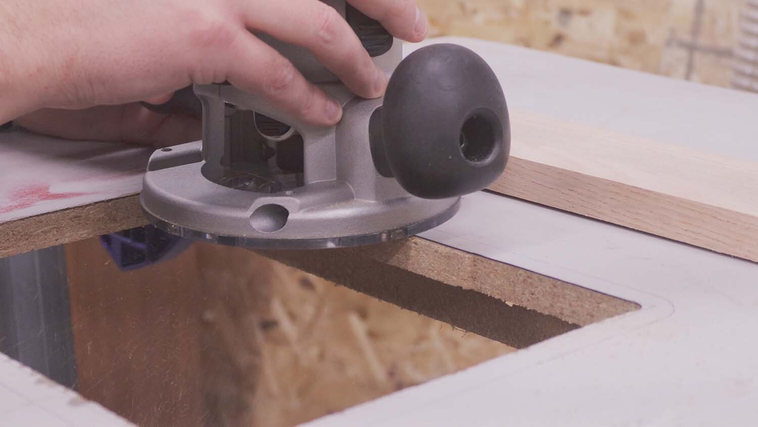
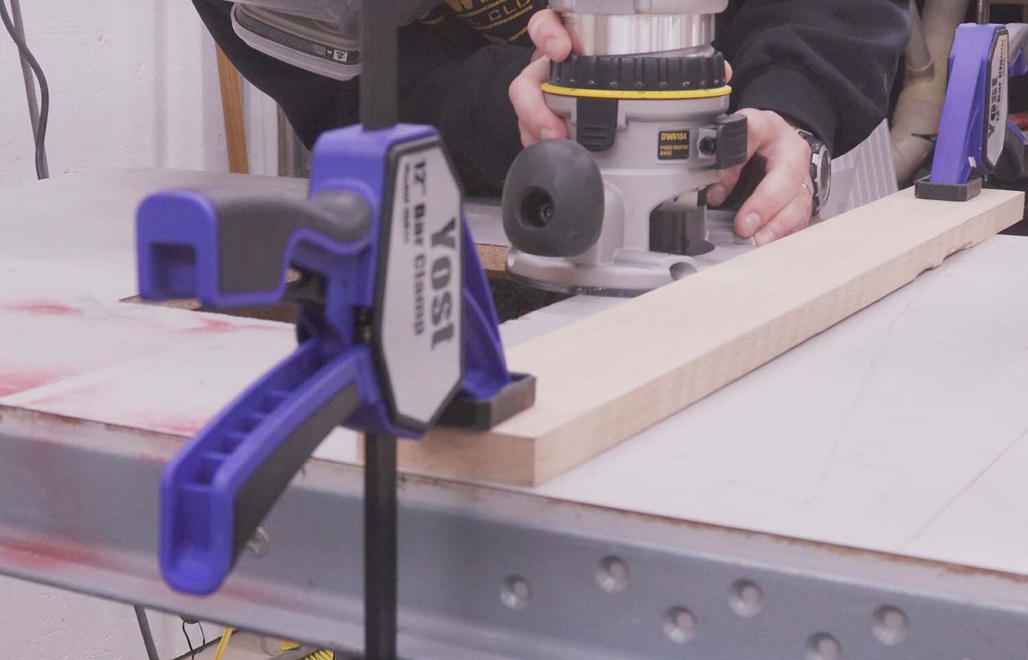
With the straight bit, I cut all four sides into a neat and precise opening, repeating the trick with the spacer and the straight guide board on the other three sides. You want to err on the side of the opening being slightly too small than too large, since you can always make it bigger.
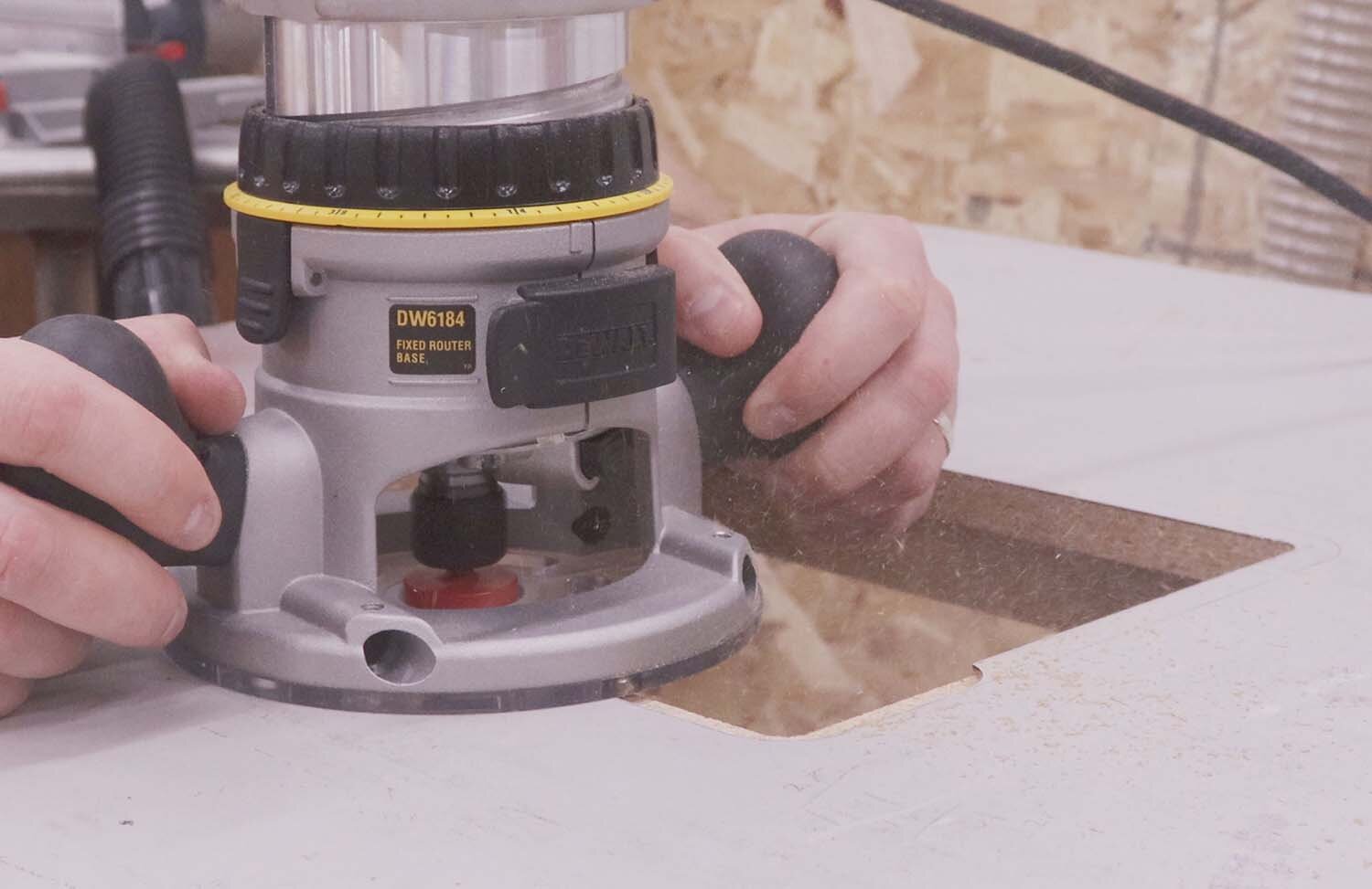
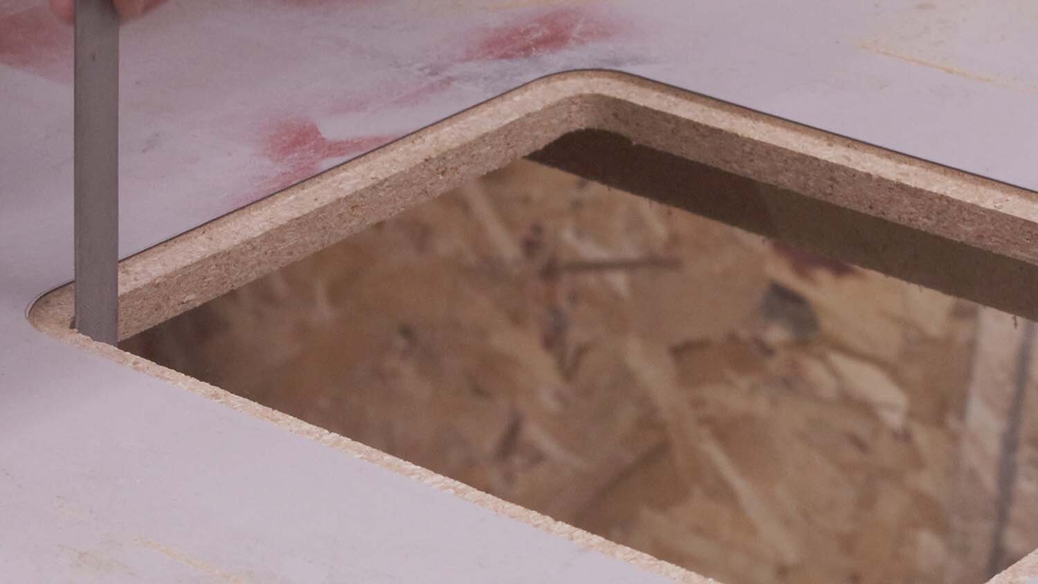
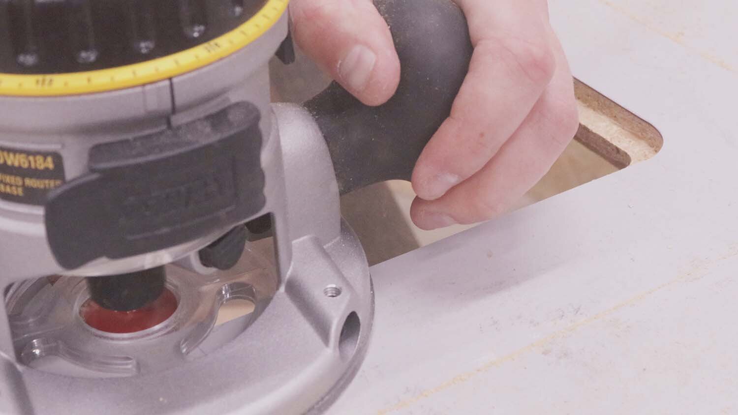
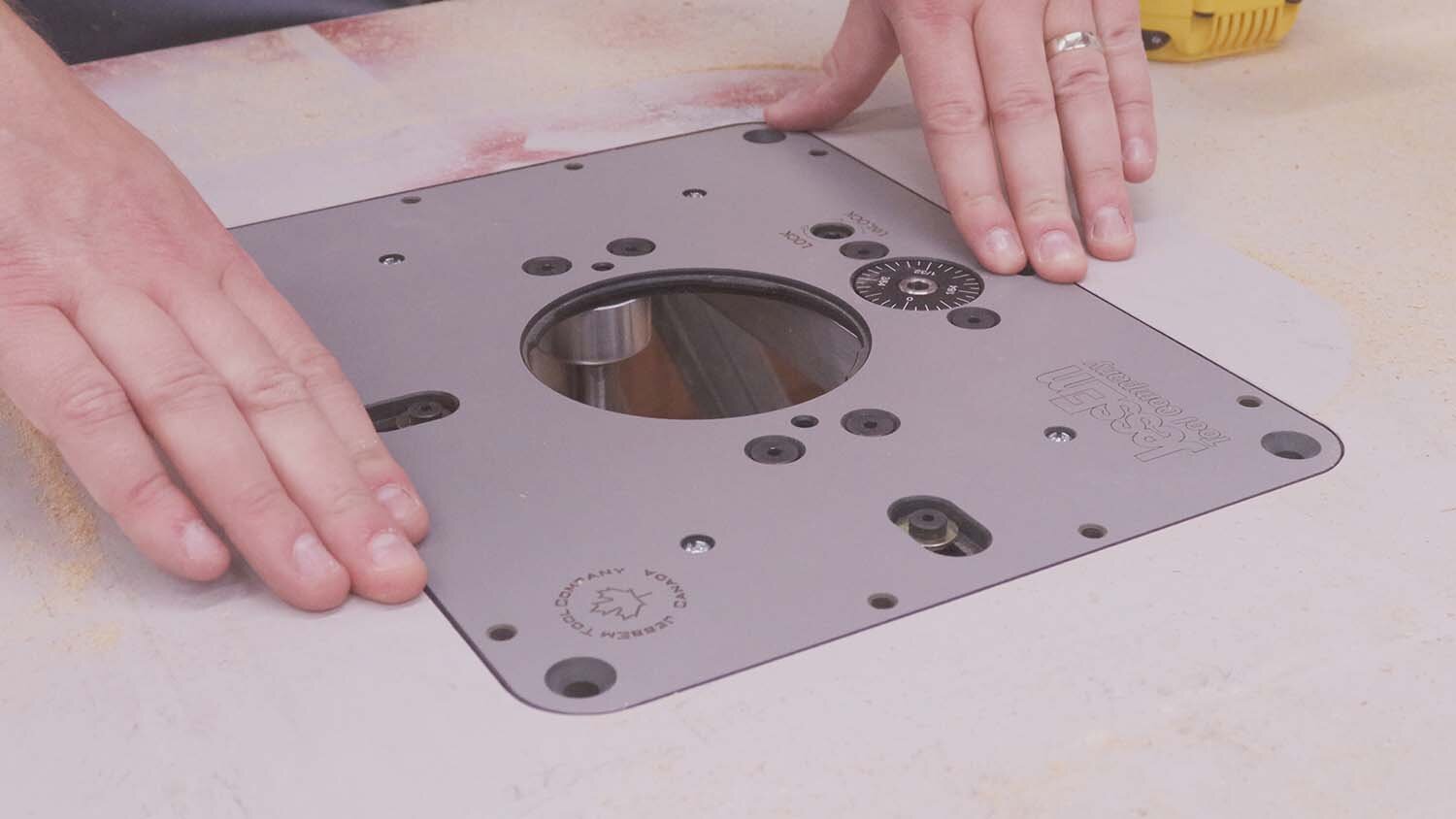
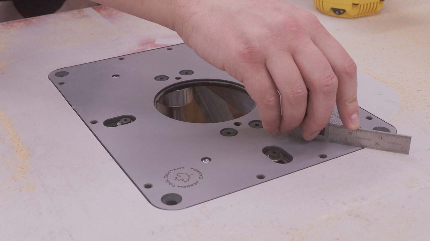
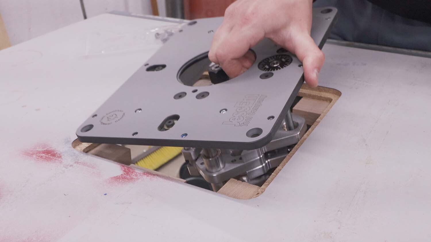
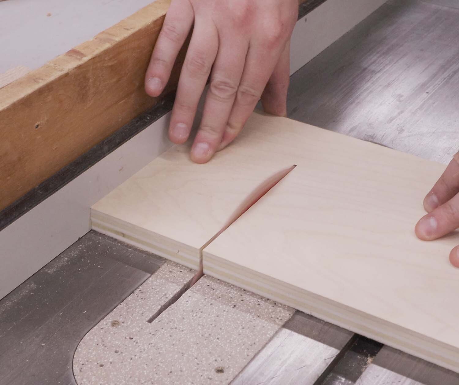
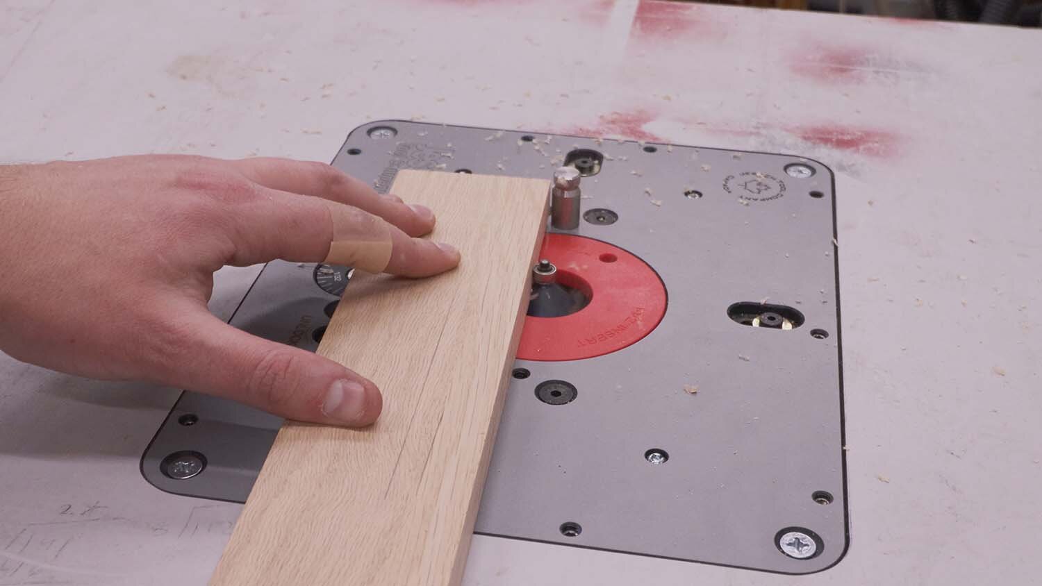
With the opening defined, I will now use the rabbeting bit to cut the recess with a shallow pass. This is to test the fit of the insert plate As you can see, the fit is a bit tight on the insert. I use a knife to mark the outline of the insert to see how much more I need to increase the opening size. Then I make the opening slightly larger using the same methods as before, and filing the corners where I need to sneak up on the fit. Now the fit is pretty much perfect!
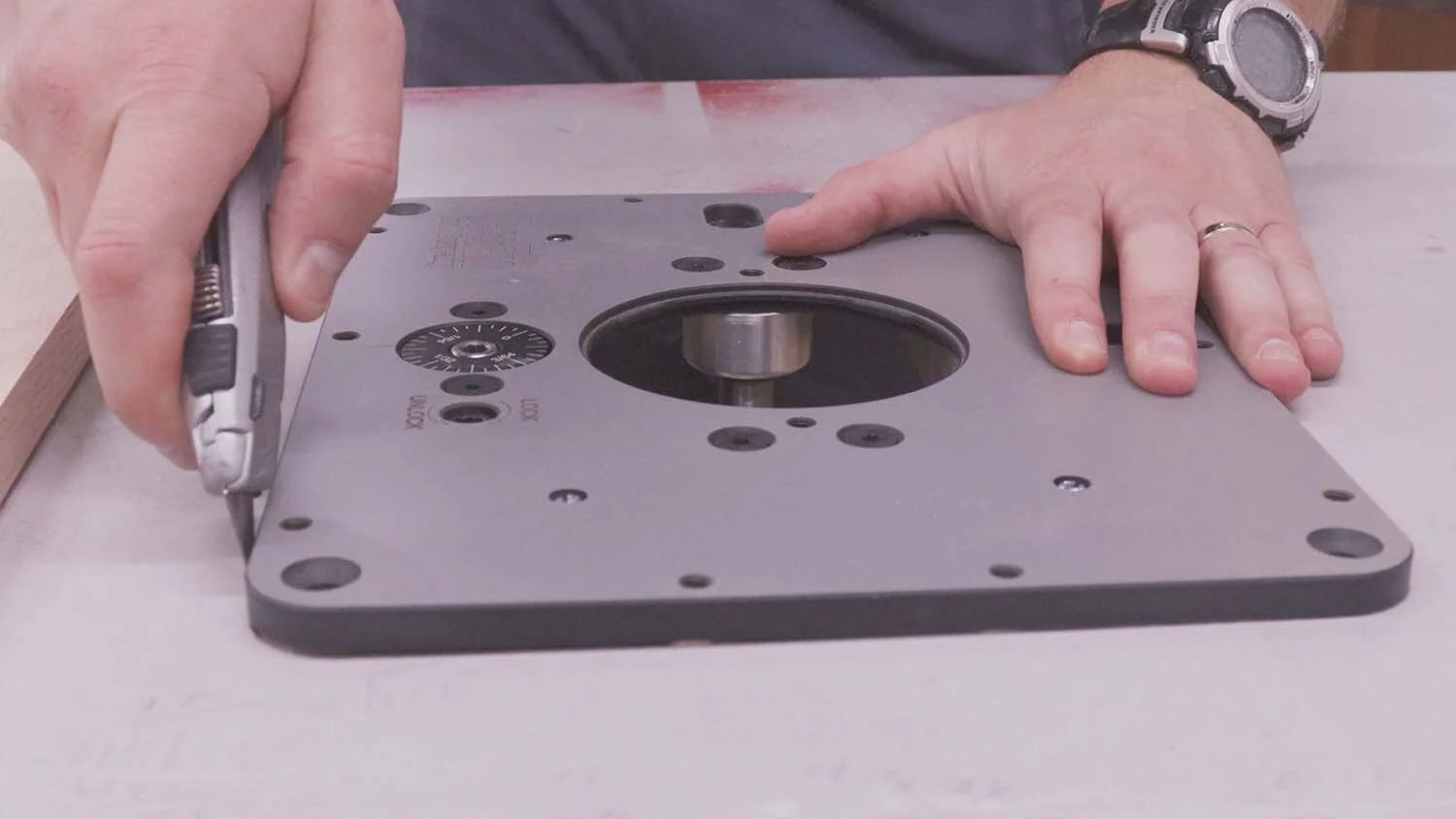
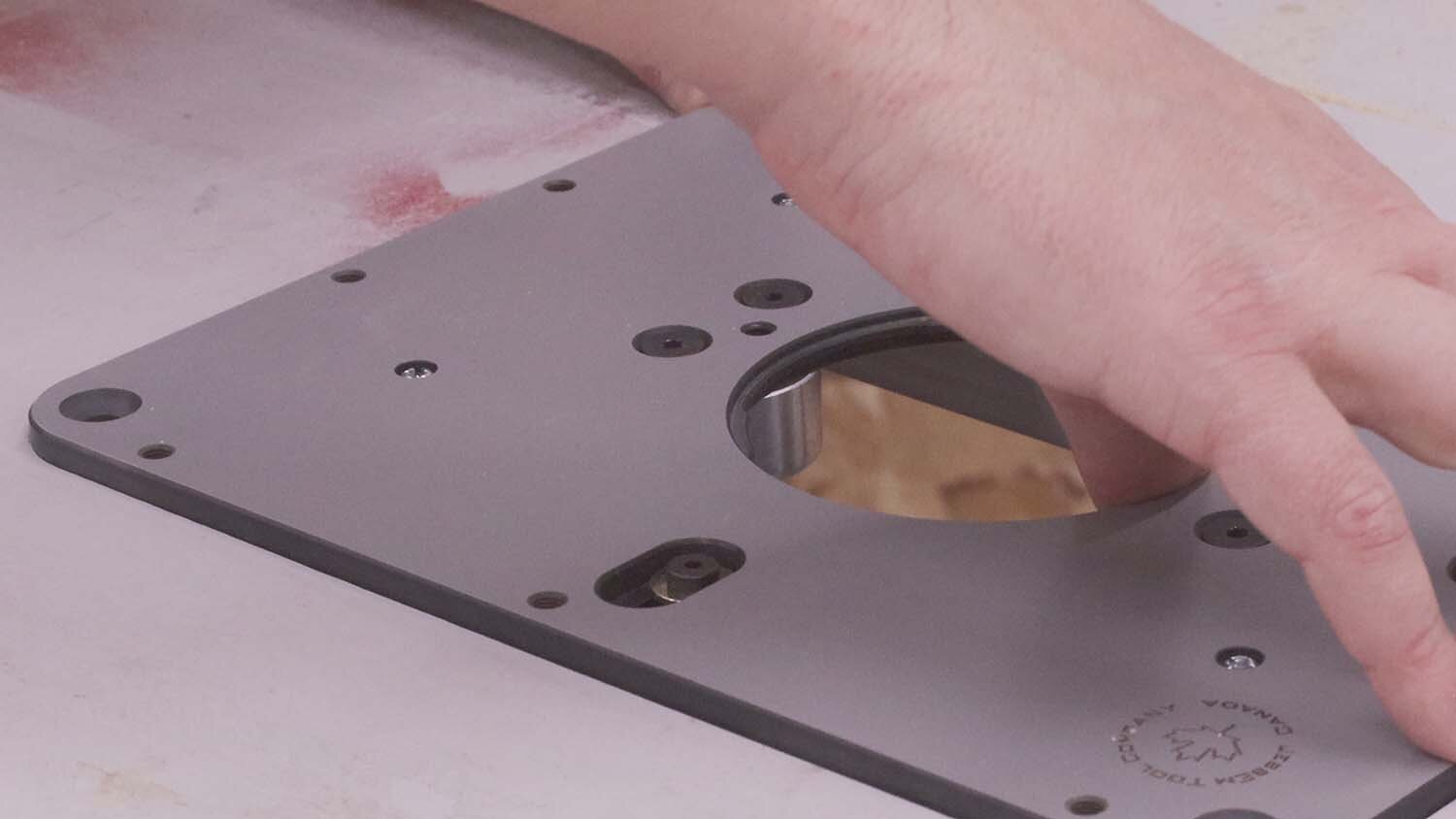
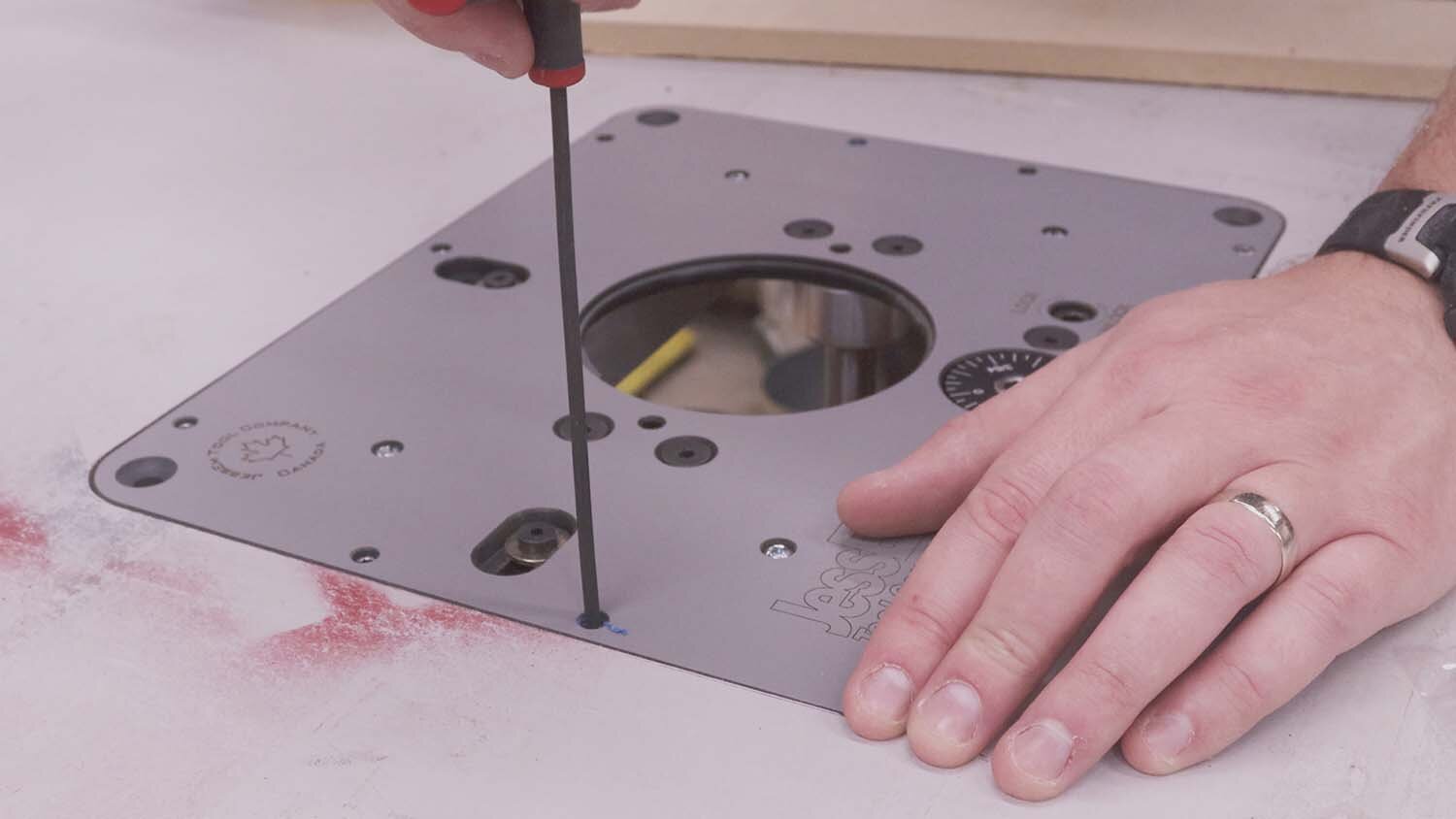
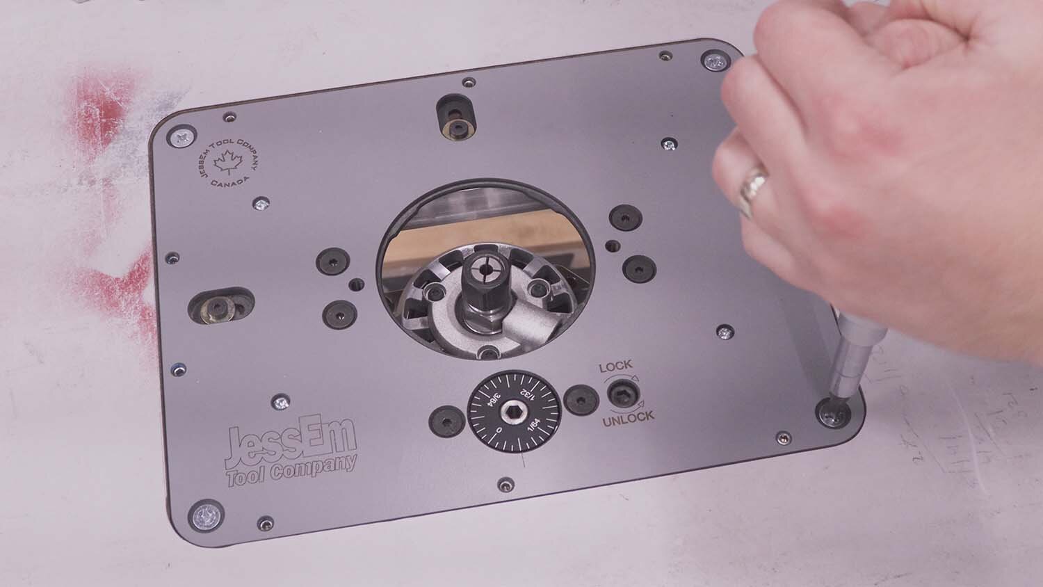
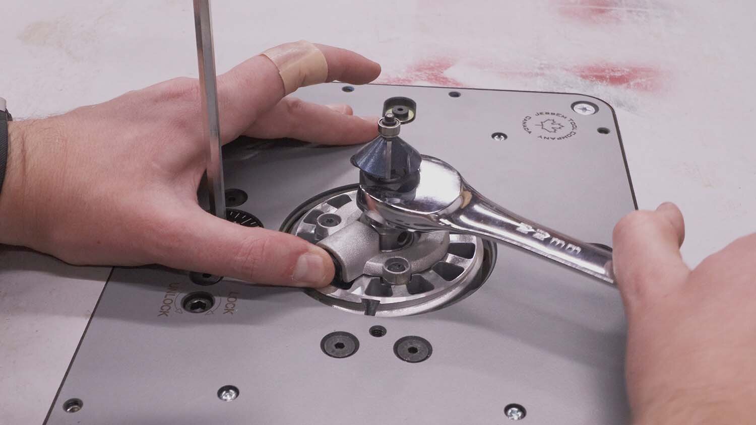
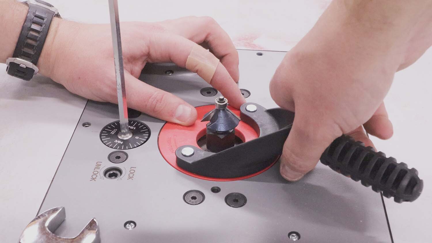
Next I set the rabbeting bit's depth of cut to be slightly deeper than the thickness of the insert, and use it to route out the recess. Since the router lift comes with leveling screws, which screw in around the perimeter of the insert, they can raise the level of the insert plate to match the tabletop. I checked that the insert was sitting flat without rocking in the recess, and that it was also flush with the tabletop.
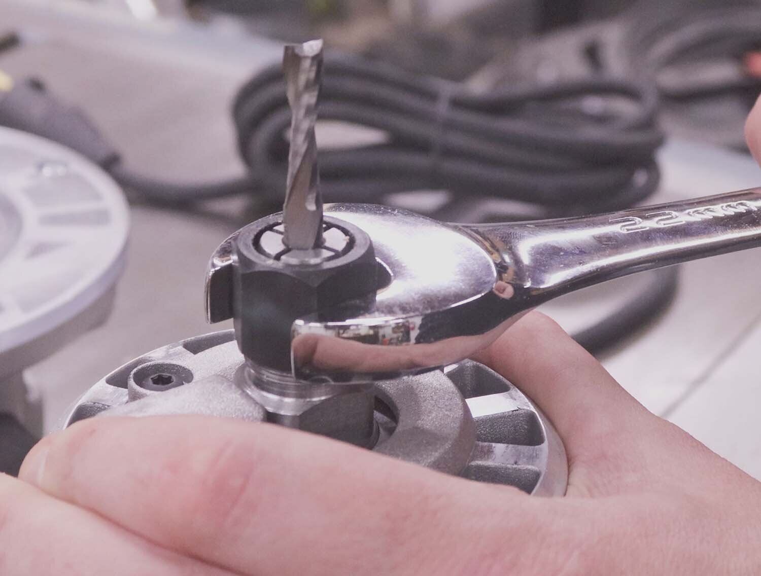
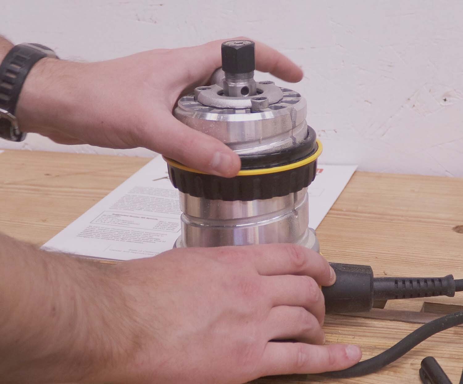
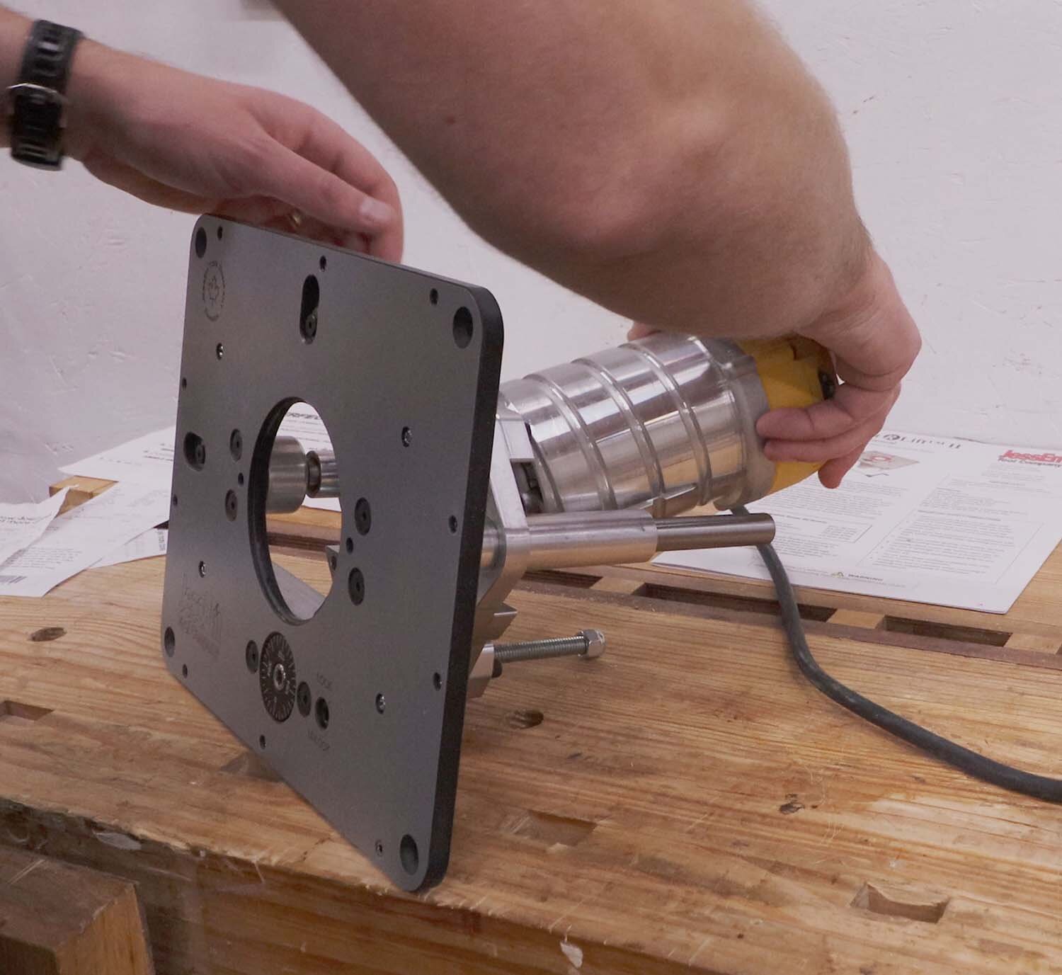
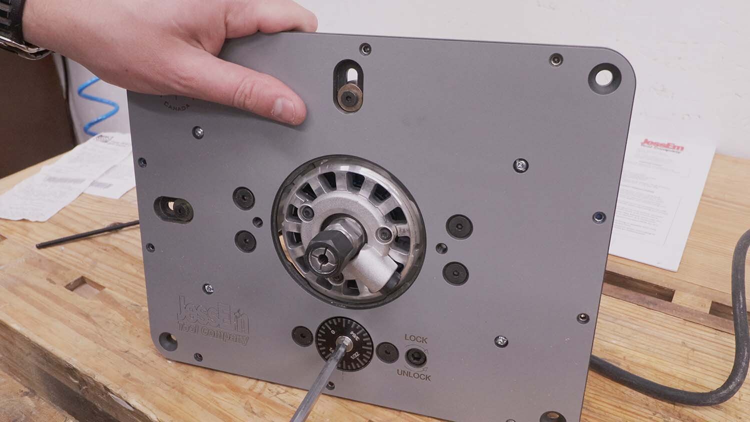
With no more need for the router base, I remove it and attach the motor body to the router lift. This is a simple matter, only needing to tighten one screw on the collar to hold the router in place.
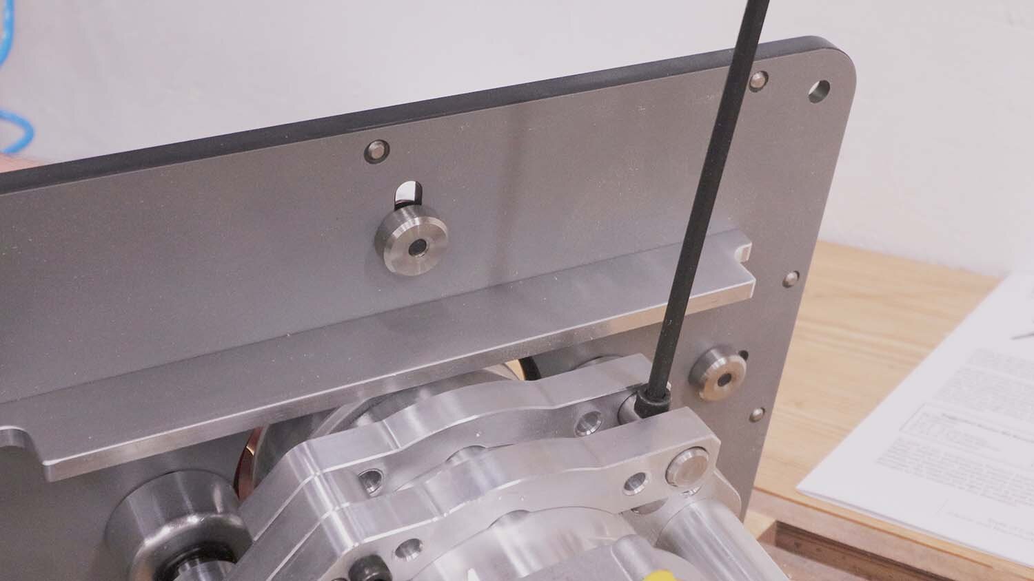
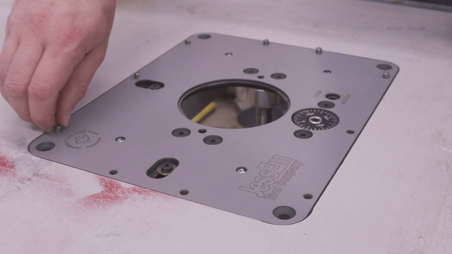
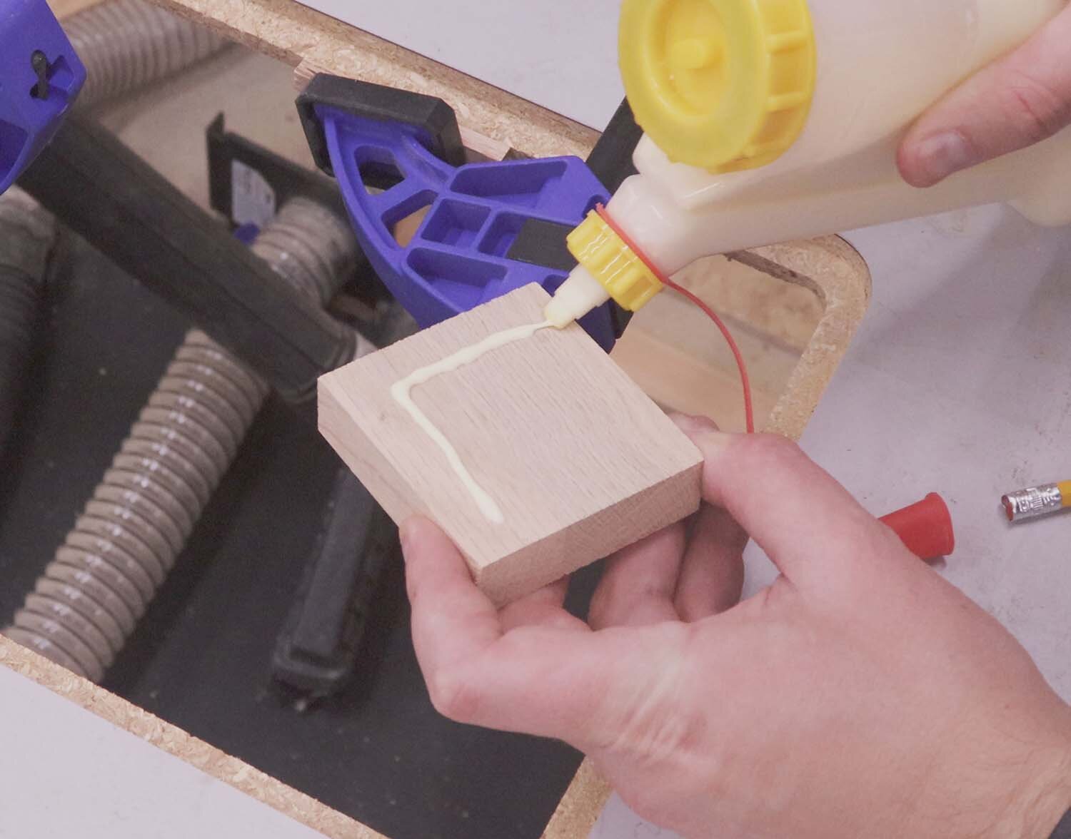
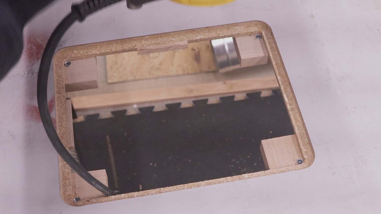
The insert has two bumpers on the sides that bear on the sides of the recess, which I need to extend out a bit with a couple scraps. Next, I add some scrap pieces to the corners for reinforcement and also for the corner mounting screws.
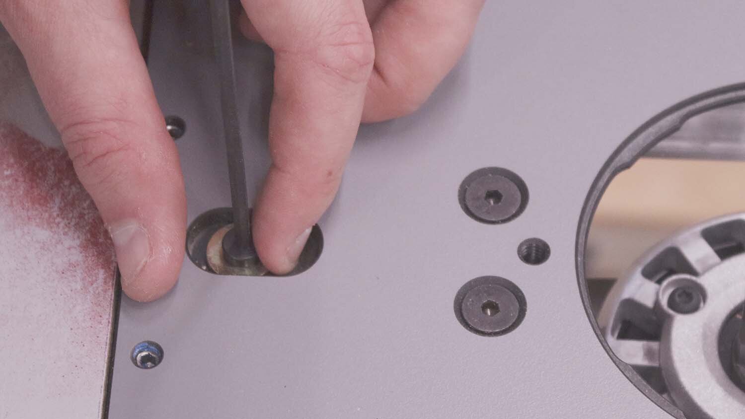
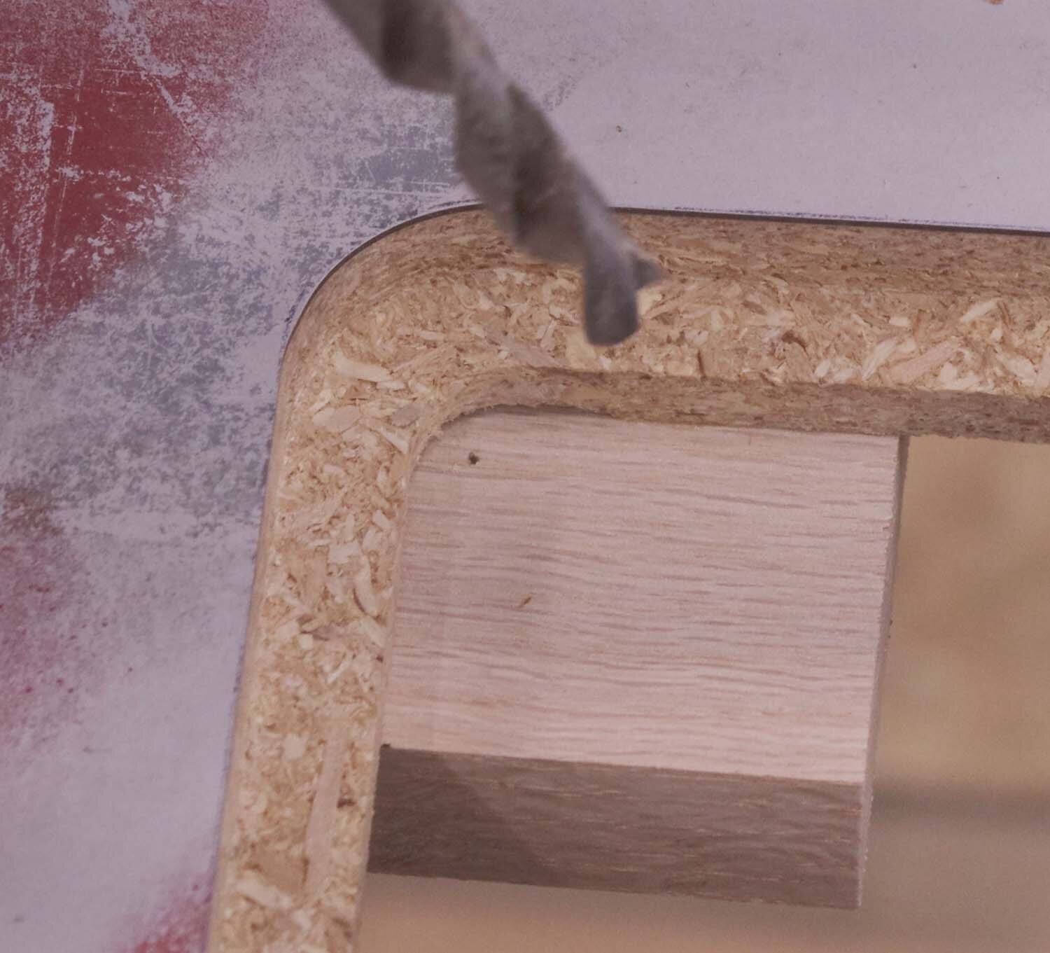
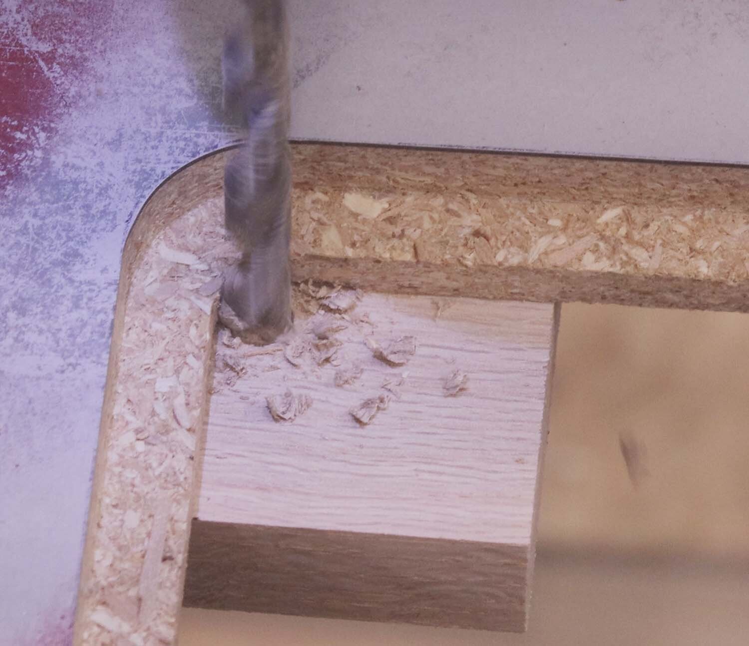
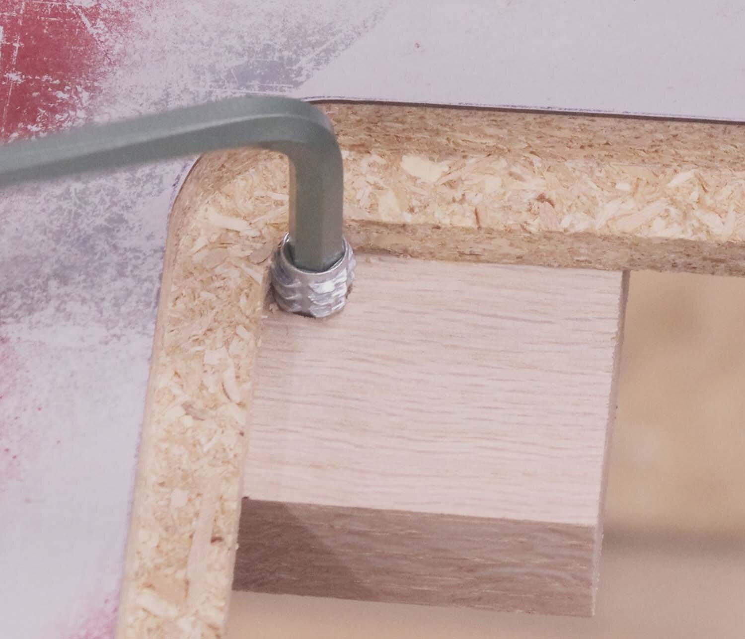
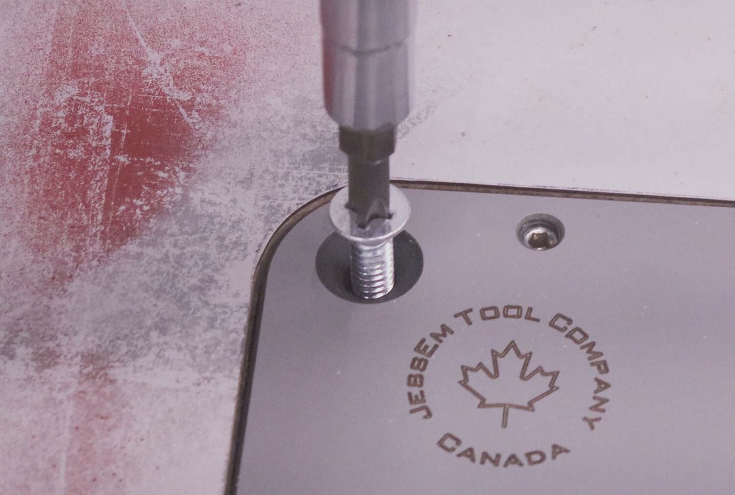
I use a brad point bit the same size as the corner holes to mark the center of these holes. Then I screw in threaded inserts in each of the corners, and use machine screws to fasten the insert to the tabletop. Careful in this step as it’s easy to over tighten these screws and bend the insert plate.
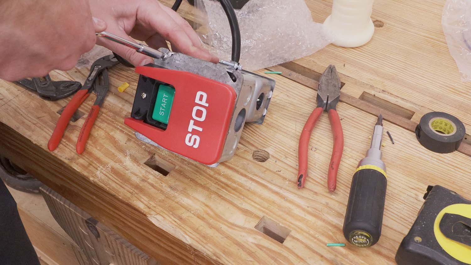
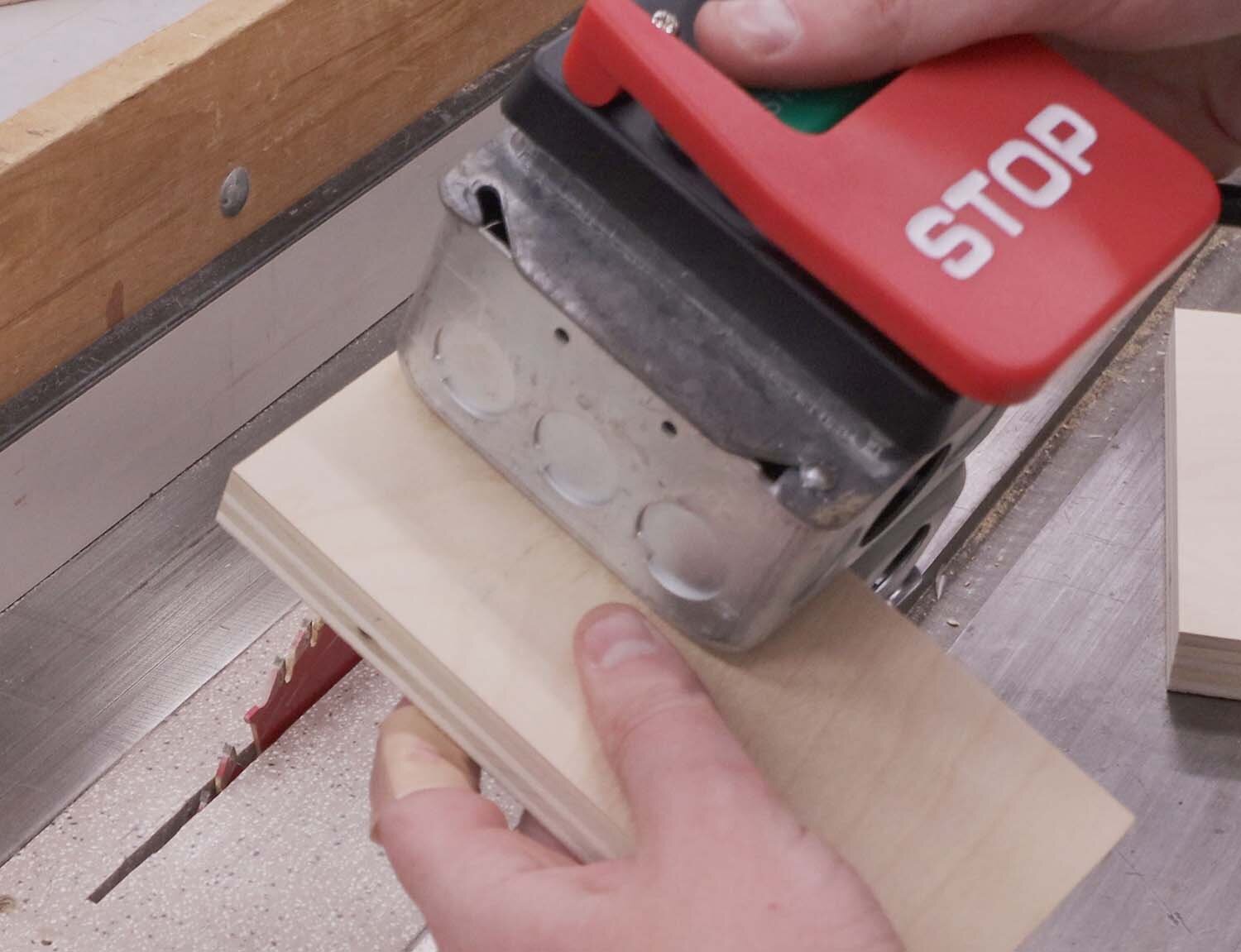
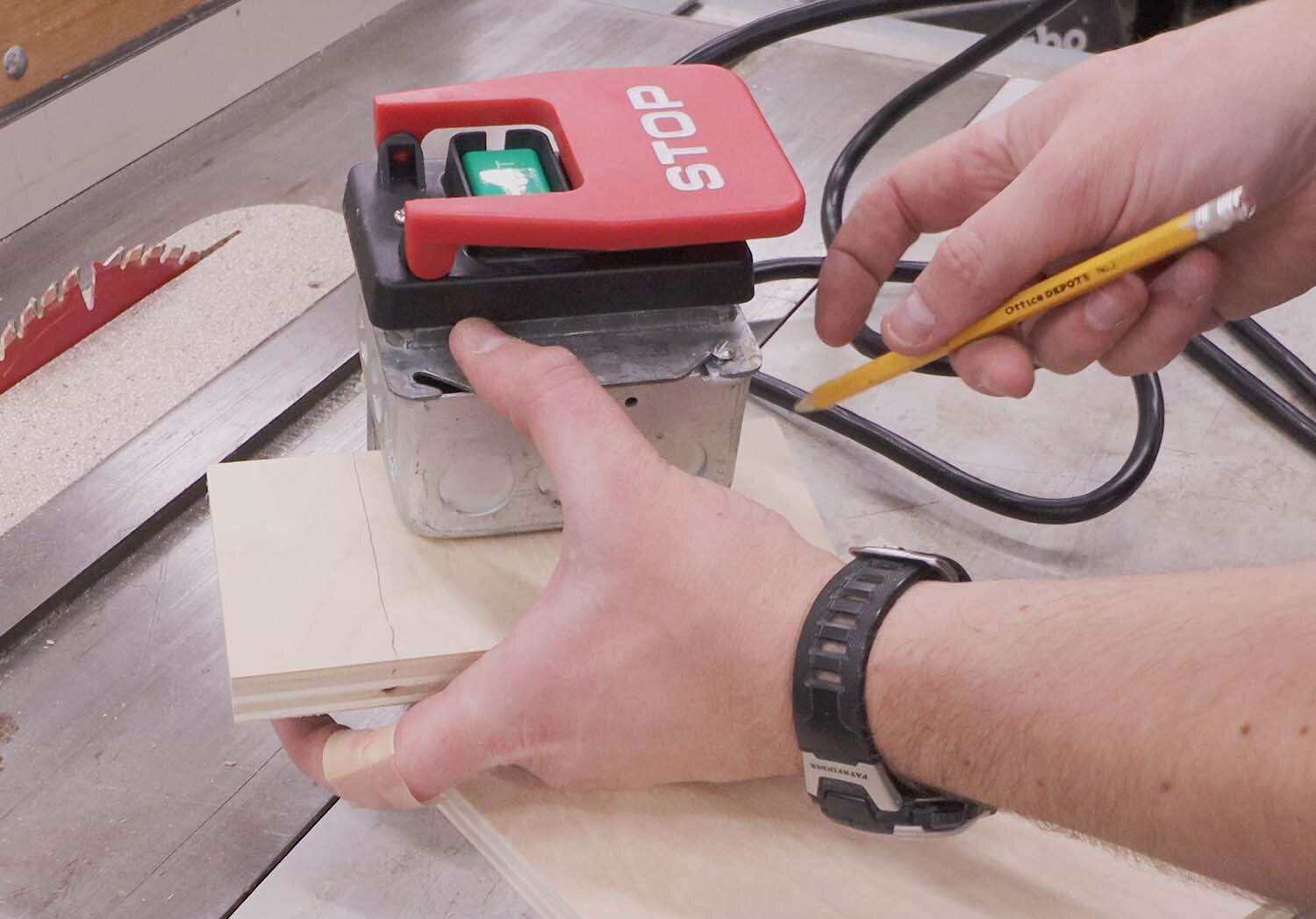
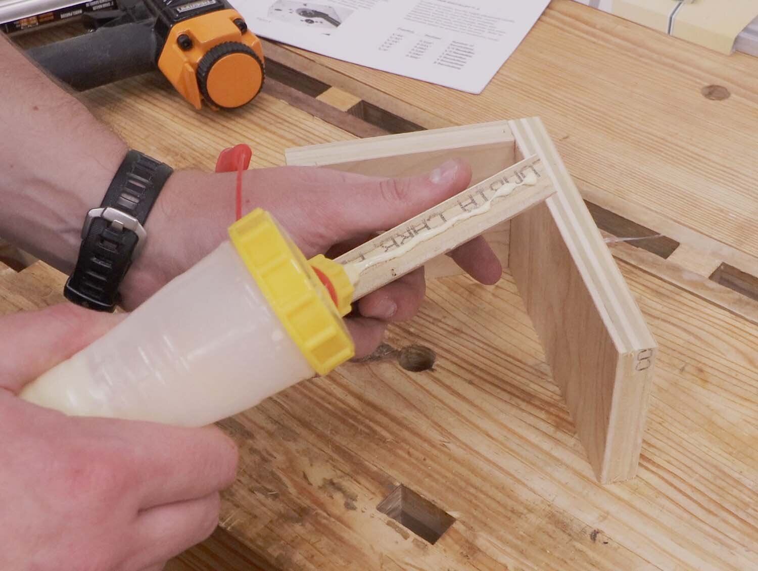
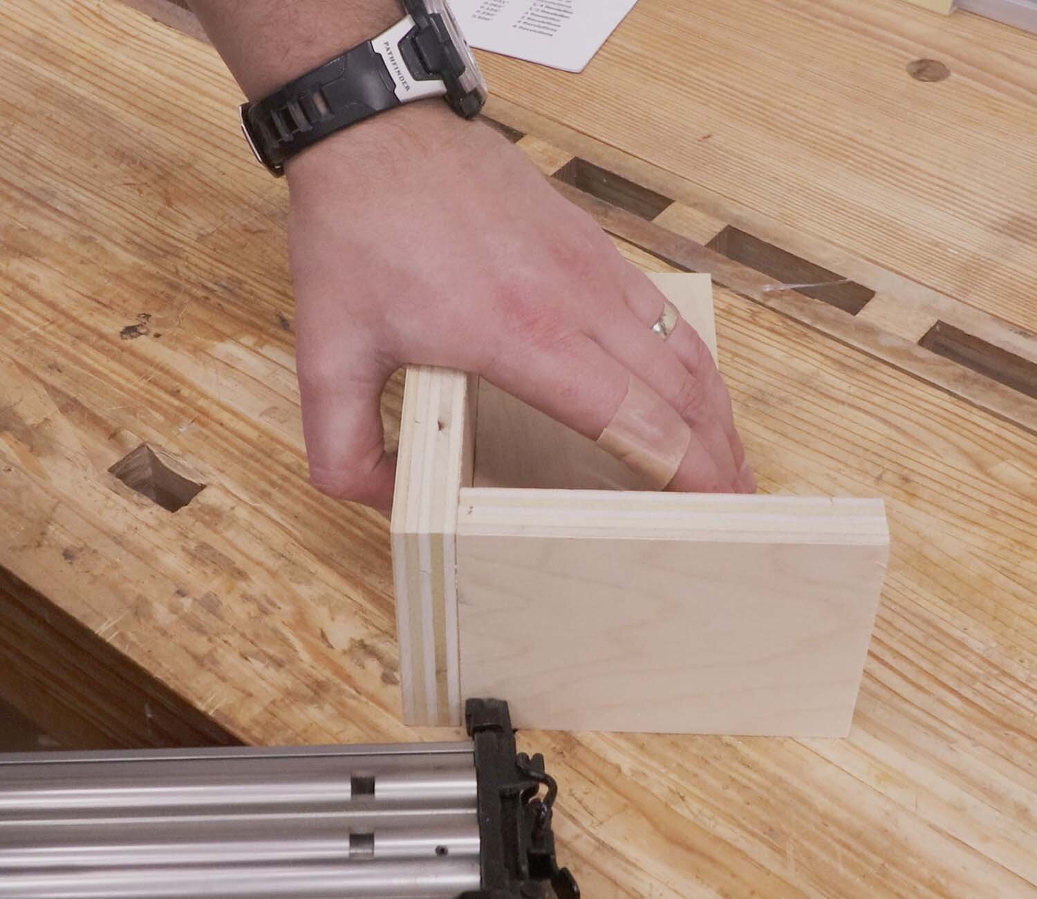
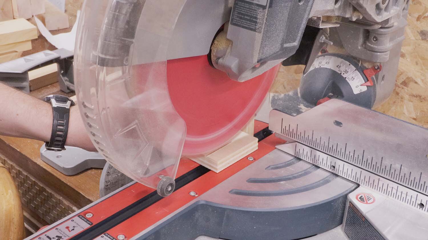
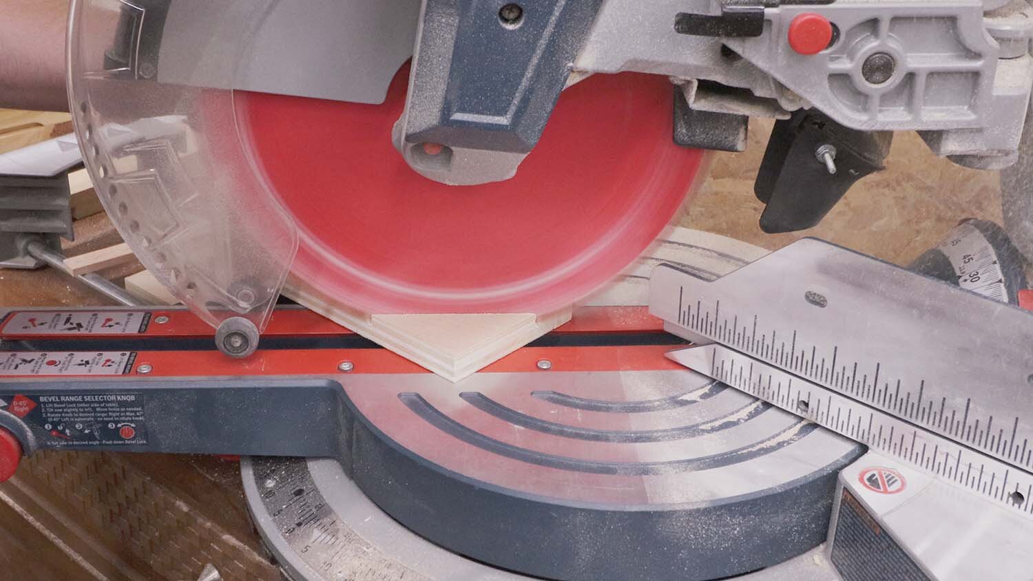
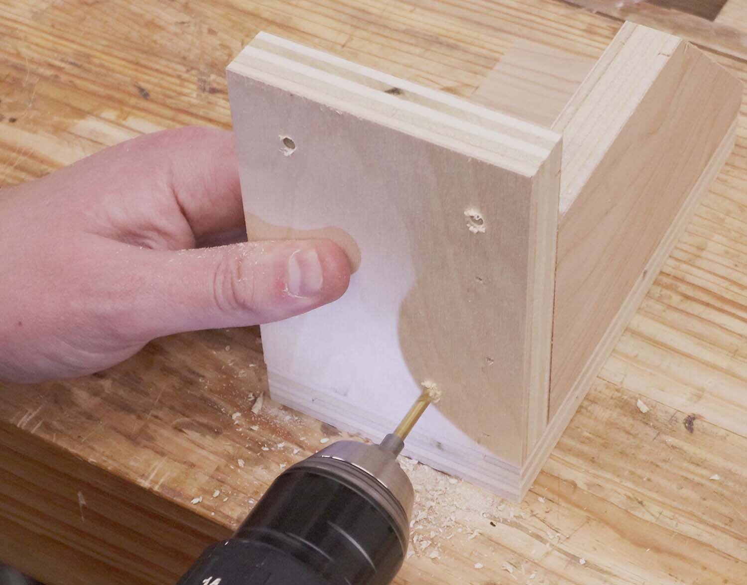
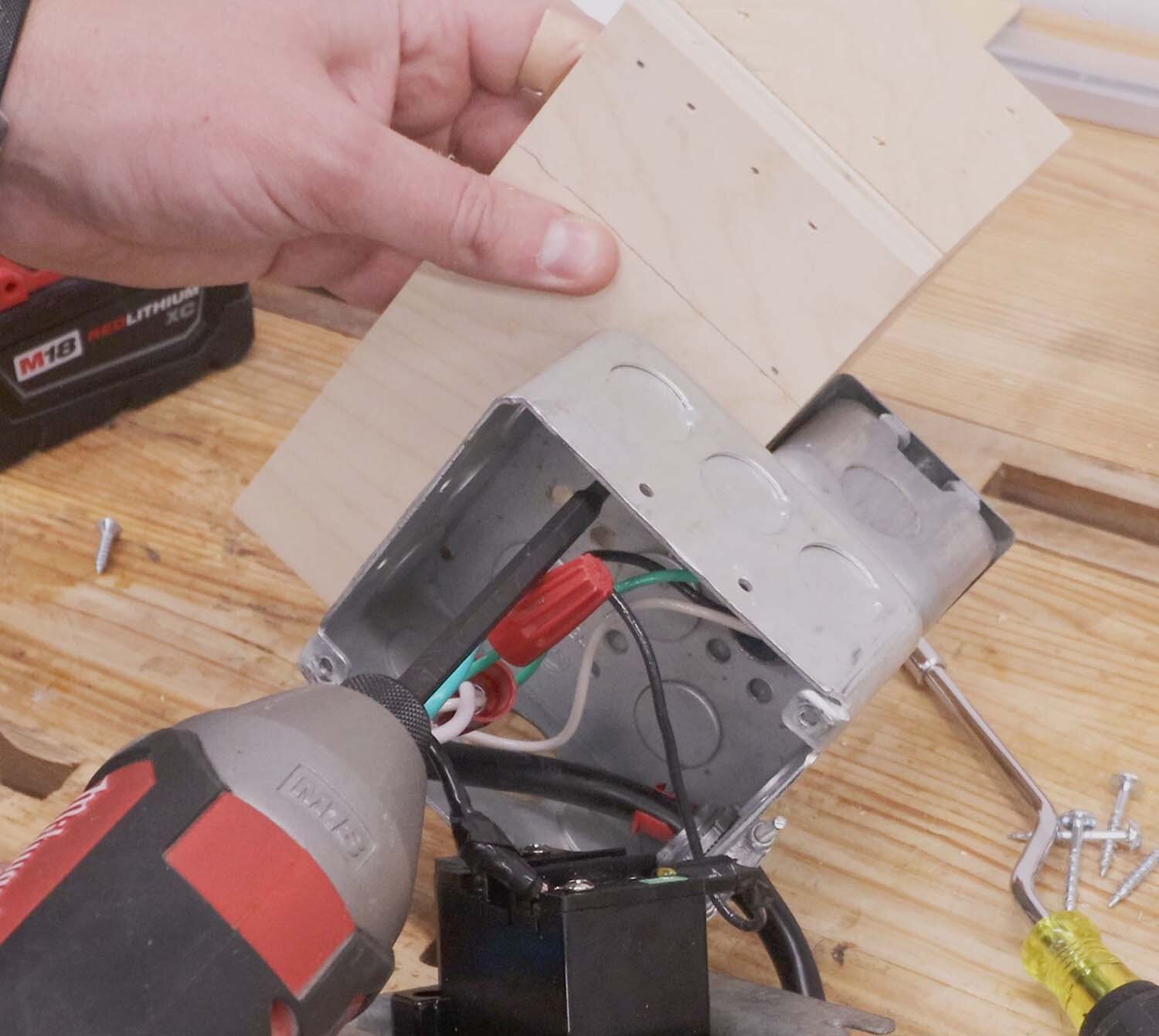
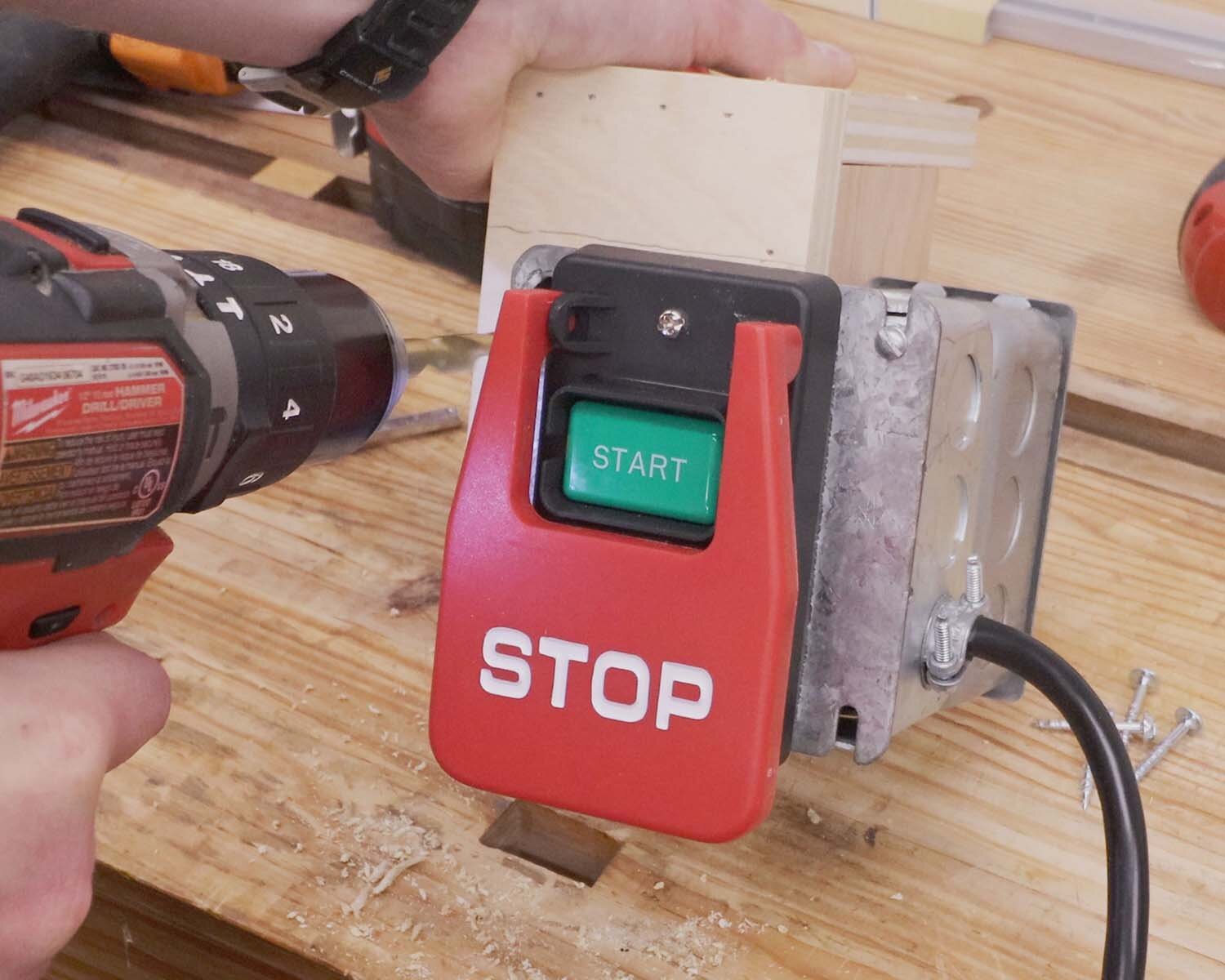
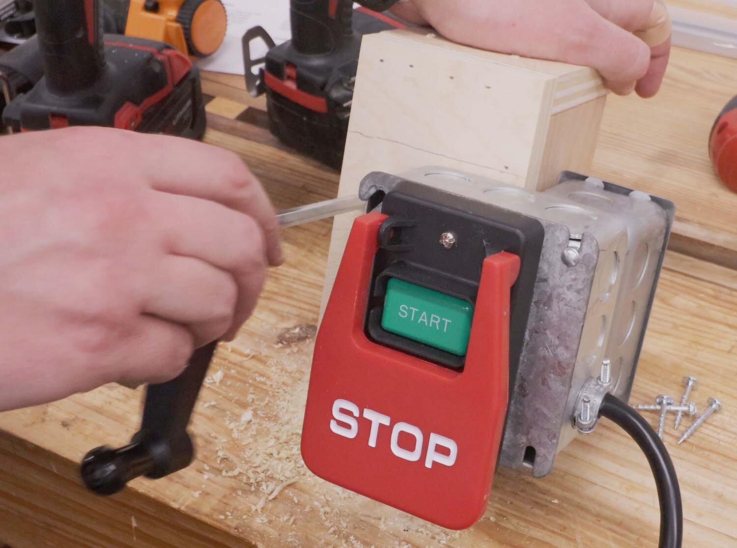
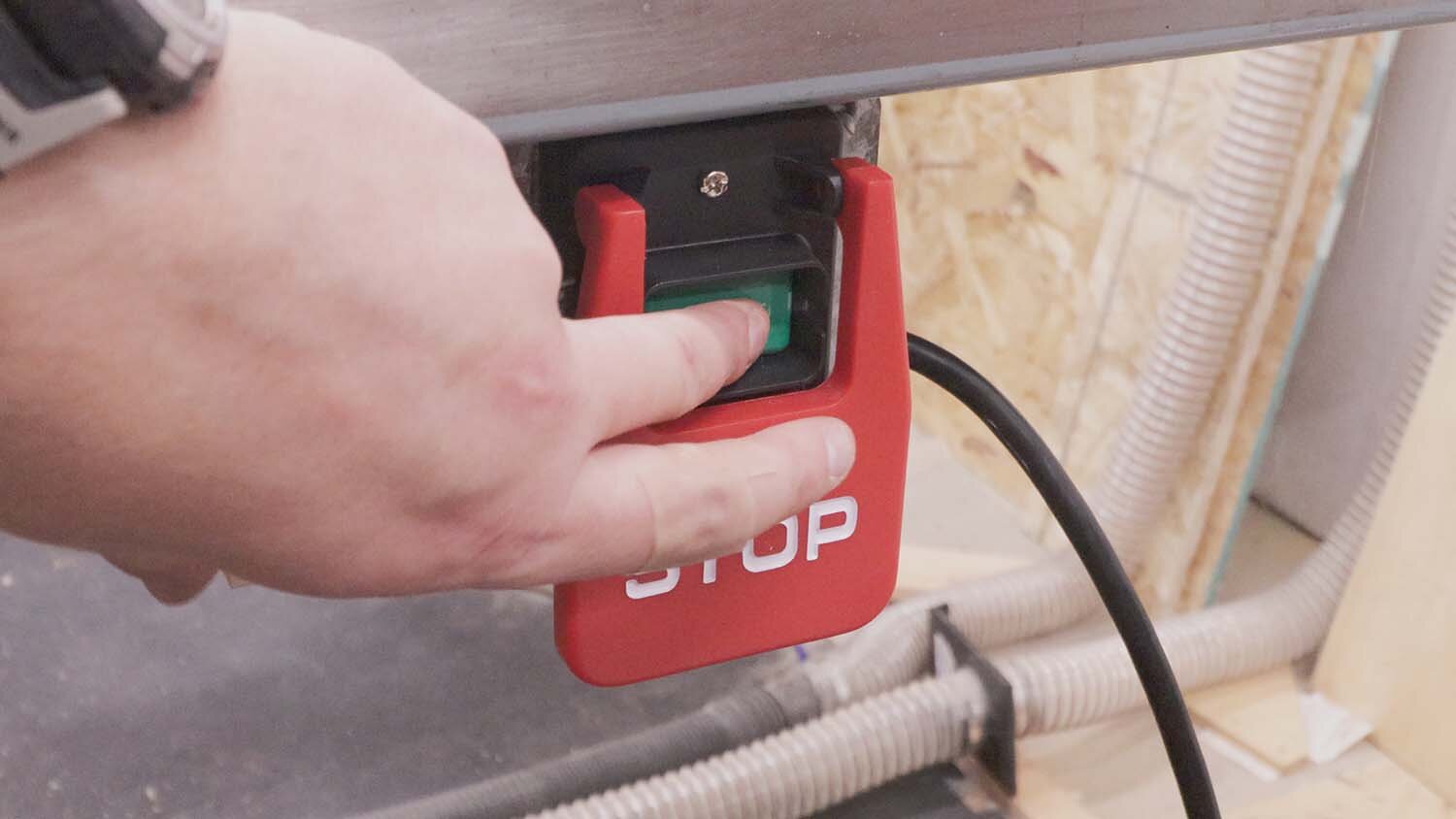
Next in the process is making the switch box for the router itself. This switch will sit under the tabletop so that I can easily hit the OFF button with my leg if need be. I covered something very similar to this already, this version just uses two back-to-back junction boxes with the wires passing between them. I then make a mount for the switch out of some scrap plywood. This mount also has a hole drilled in it to hold the crank handle in a convenient spot.

With everything wired up, all that's left to do it try it out! I'm really excited to have this router lift finally installed in my workshop. I know it's going to see a lot of use in the future.
I hope this was instructive, and thanks for viewing!
If you enjoyed this article, subscribe to my YouTube channel for more!
—————————————————————————————
Below is a listing of the supplies you will need. I have supplied Amazon Affiliate links to the products I used. As an Amazon Associate I earn from qualifying purchases.