
DIY Portable Switched Outlet
In this article, I’ll be making a safe, robust, portable switched power supply from commonly available parts. These are very handy to have around the workshop, especially when you need to control tools without an on/off switch, or where the switch is in an inconvenient location. They're also helpful for workbenching, where you need a convenient way to control power to a tool or assembly you're testing.
𝗨𝗣𝗗𝗔𝗧𝗘 𝗥𝗘𝗚𝗔𝗥𝗗𝗜𝗡𝗚 𝗘𝗟𝗘𝗖𝗧𝗥𝗜𝗖𝗔𝗟 𝗖𝗢𝗗𝗘: I recently became aware of National Electrical Code (NEC) Section 525.23. One pertinent Provision of this, which was added in the 2017 revision to the NEC, reads:
(𝗗) 𝗥𝗲𝗰𝗲𝗽𝘁𝗮𝗰𝗹𝗲𝘀 𝗦𝘂𝗽𝗽𝗹𝗶𝗲𝗱 𝗯𝘆 𝗣𝗼𝗿𝘁𝗮𝗯𝗹𝗲 𝗖𝗼𝗿𝗱𝘀. Where GFCI protection is provided through the use of GFCI receptacles, and the branch circuits supplying receptacles utilize flexible cord, the GFCI protection shall be listed, labeled, and identified for portable use.
Section 525.23 has other verbiage regarding GFCI protection that may be worth reading. As always, you work at your own risk. Don't take electrical wiring advise solely from some guy on the internet.
I made this portable outlet specifically to control power to my table-mounted portaband saw, which has a finger trigger for power. When table-mounted, it's far easier to clamp the trigger down and control power with a switch.

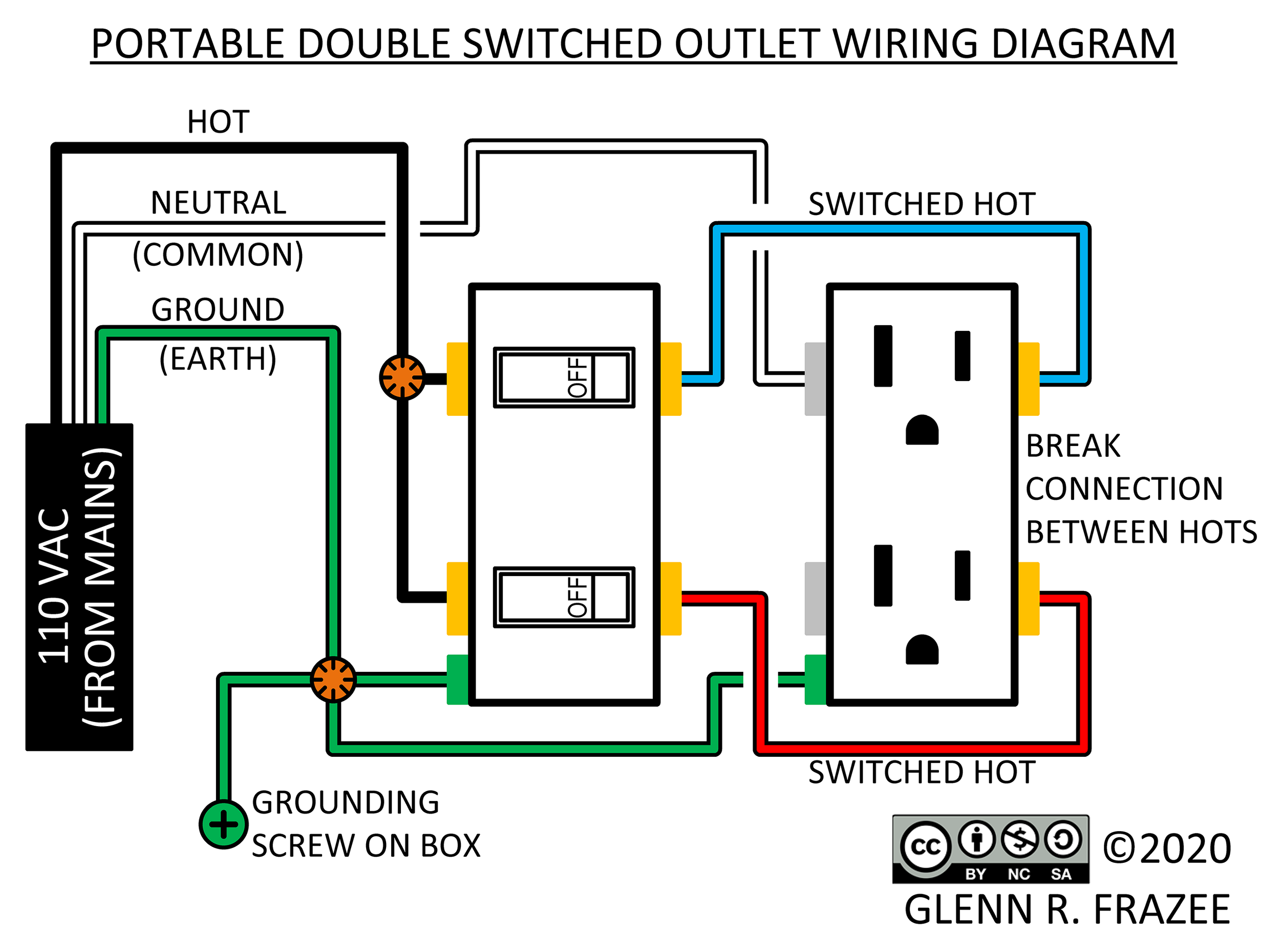
Before getting into things, let’s review the wiring diagram. On the left, we have power coming in from the power cord, with the black wire being hot, white being neutral, and green being ground. The hot wire is fed into the switch, and when you flip the switch, power goes to the receptacle. The circuit is completed via the neutral wire attached on the other side of the receptacle.

Note that this concept can be applied to make a double-switched power supply, where one switch controls only one outlet of the duplex receptacle. There are a couple more steps and additional wires needed to make this type, but it’s really no more complicated than what we're building here.
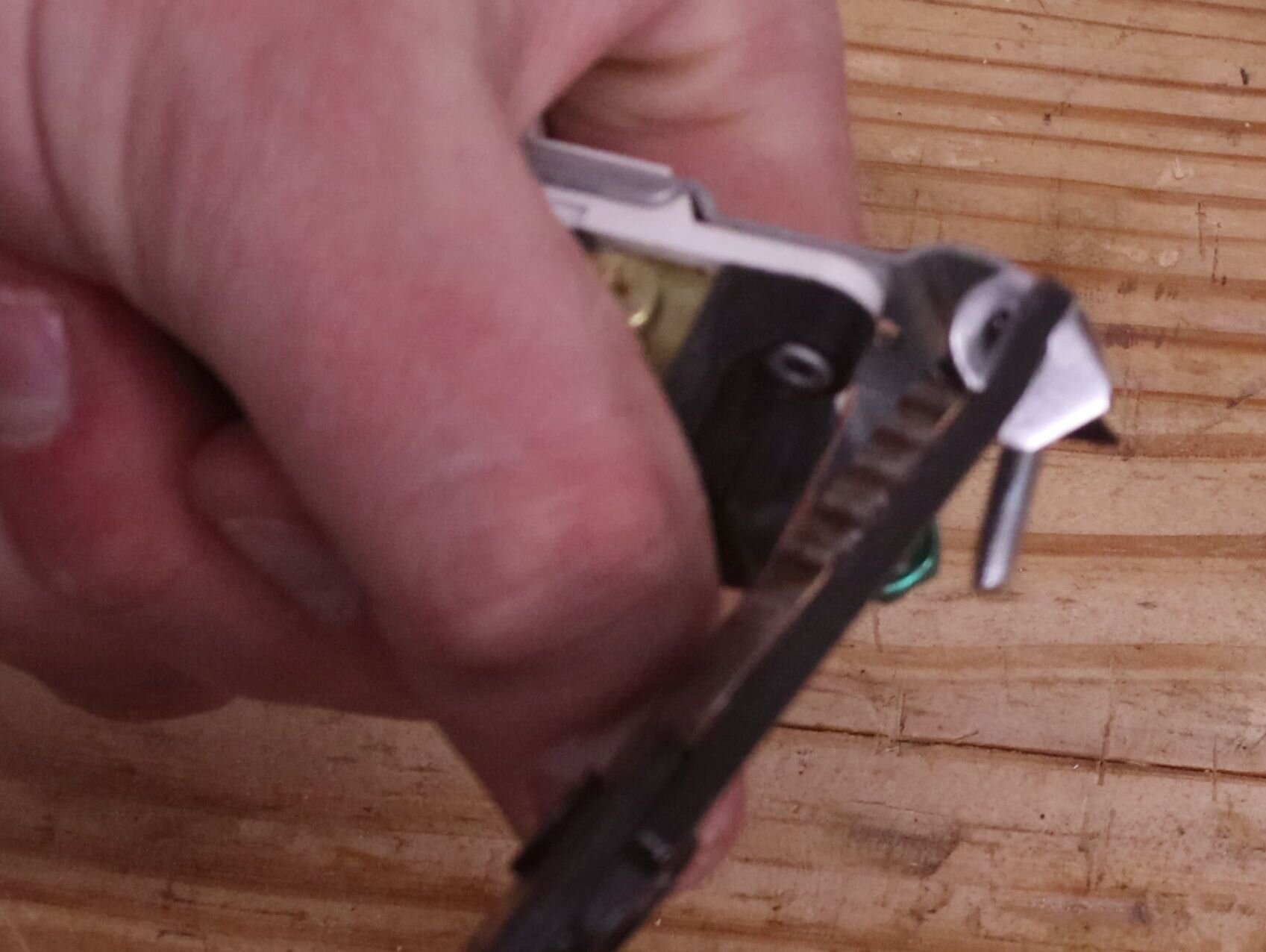
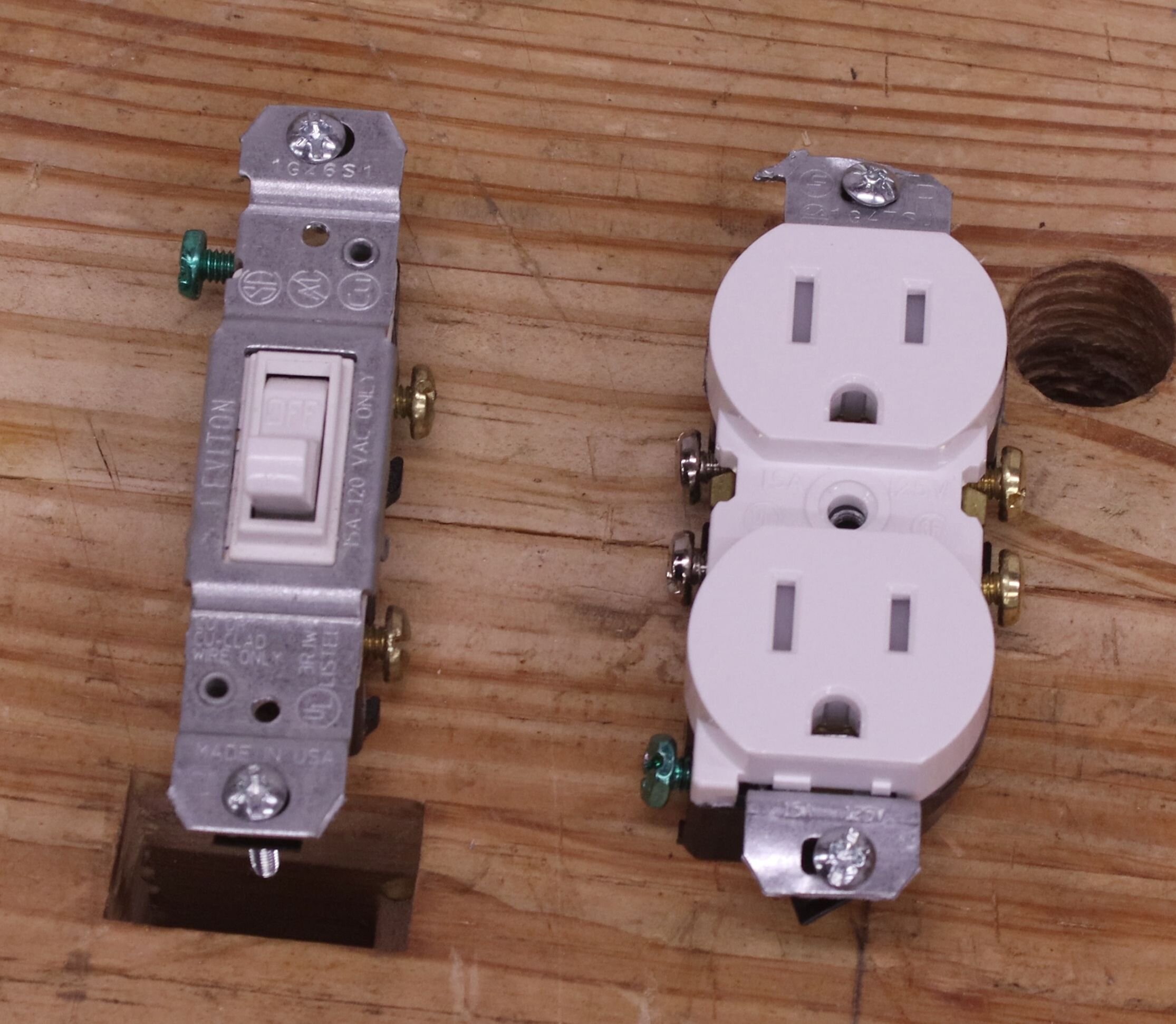
To start off, we’ll need to bend off the tabs on the receptacle and the switch. These are used when wall-mounting to keep proper spacing off of drywall, but they get in the way of the exposed work cover we’ll use later. Use the pliers to bend the tabs back and forth until the metal fatigues and snaps off.
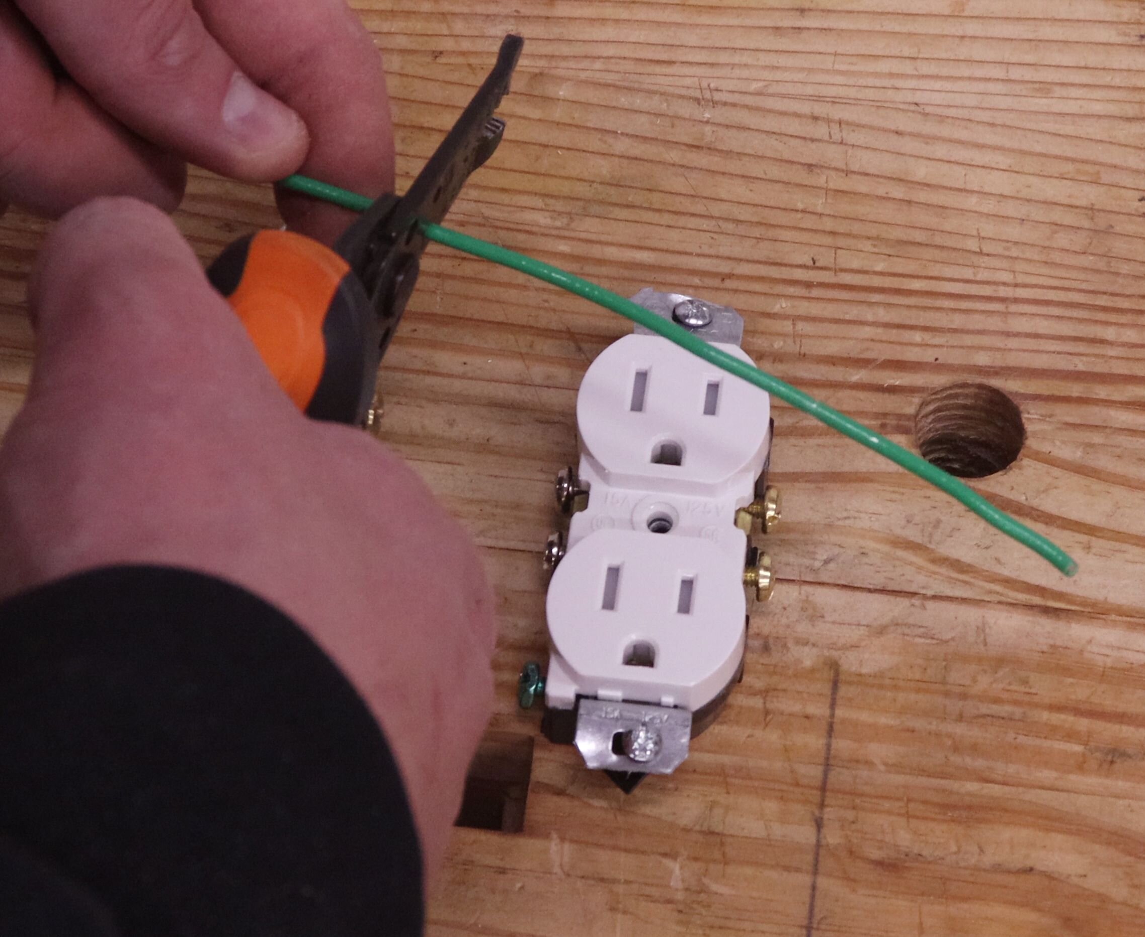
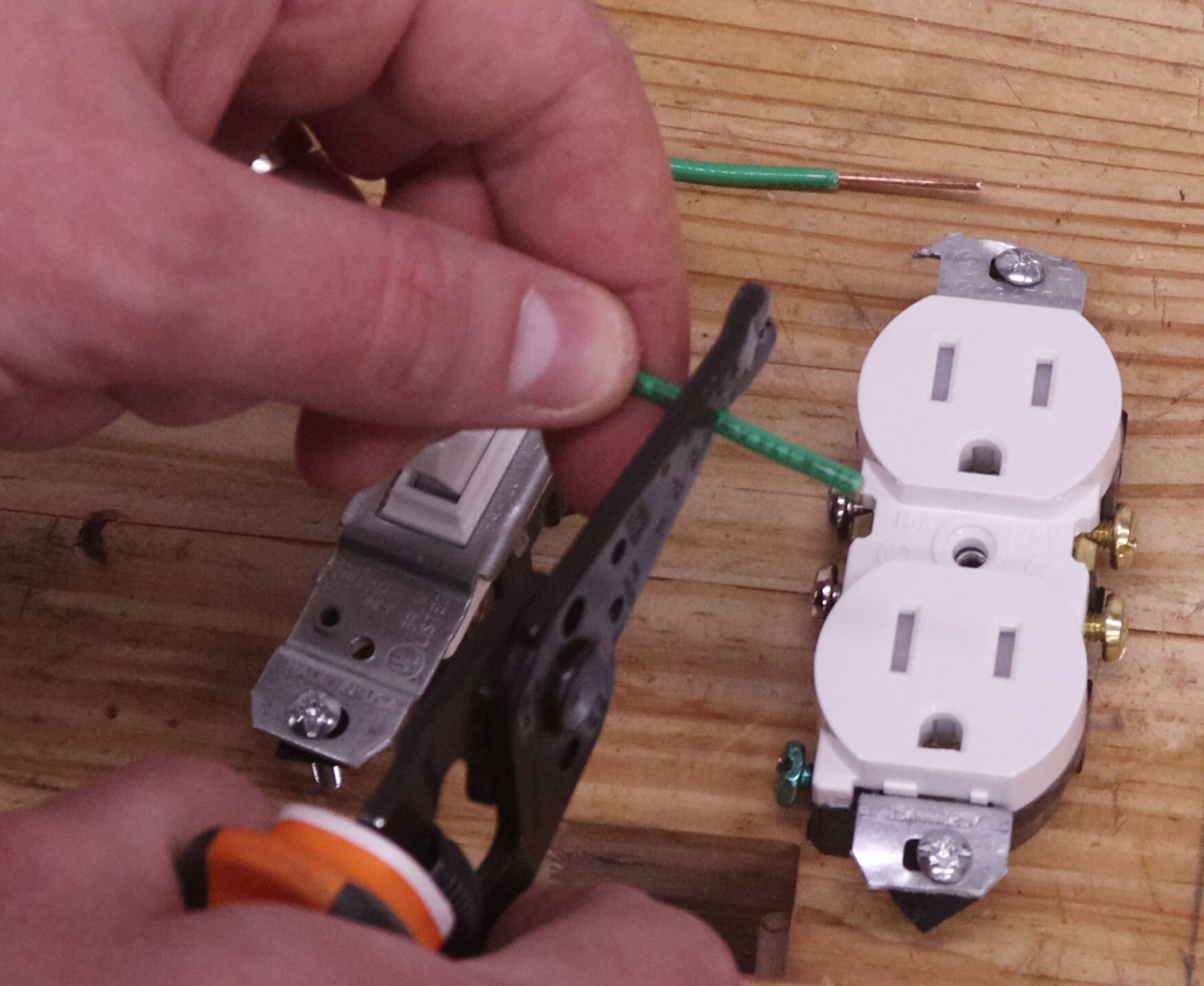
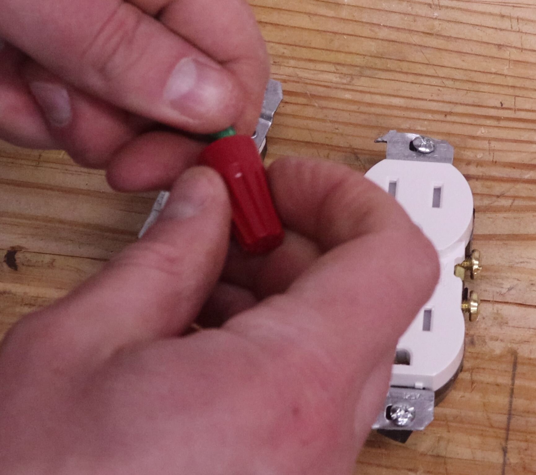
Take the 18″ (450 mm) length of green wire and snip it into three six-inch (150-mm) lengths. Strip about 3/4″ (19 mm) off one end of each of the wires. Then, using the lineman’s pliers, twist together two of the wires. With those twisted, add in the third wire. Then cap everything off temporarily with the wire nut. Note: don't just jam all the wires into the wire nut and expect it to hold things together - the wires need to be pre-twisted together before applying the wire nut.
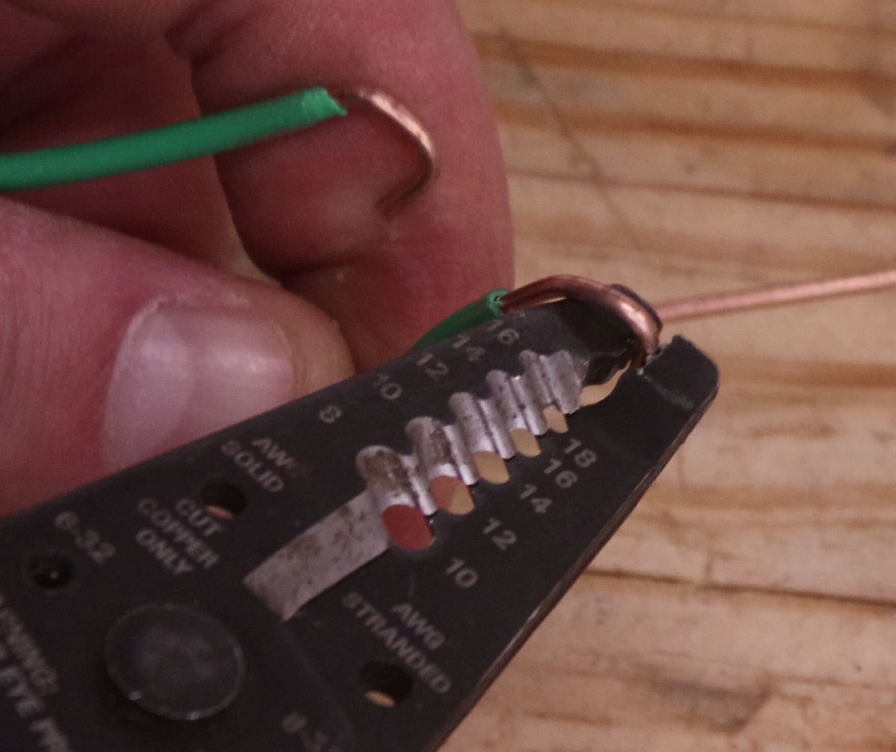
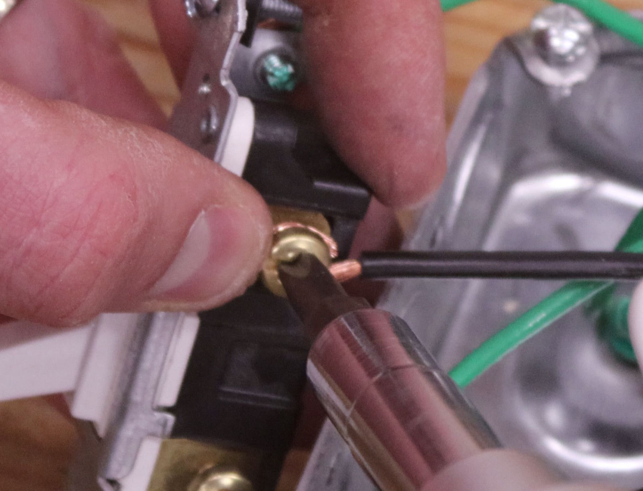
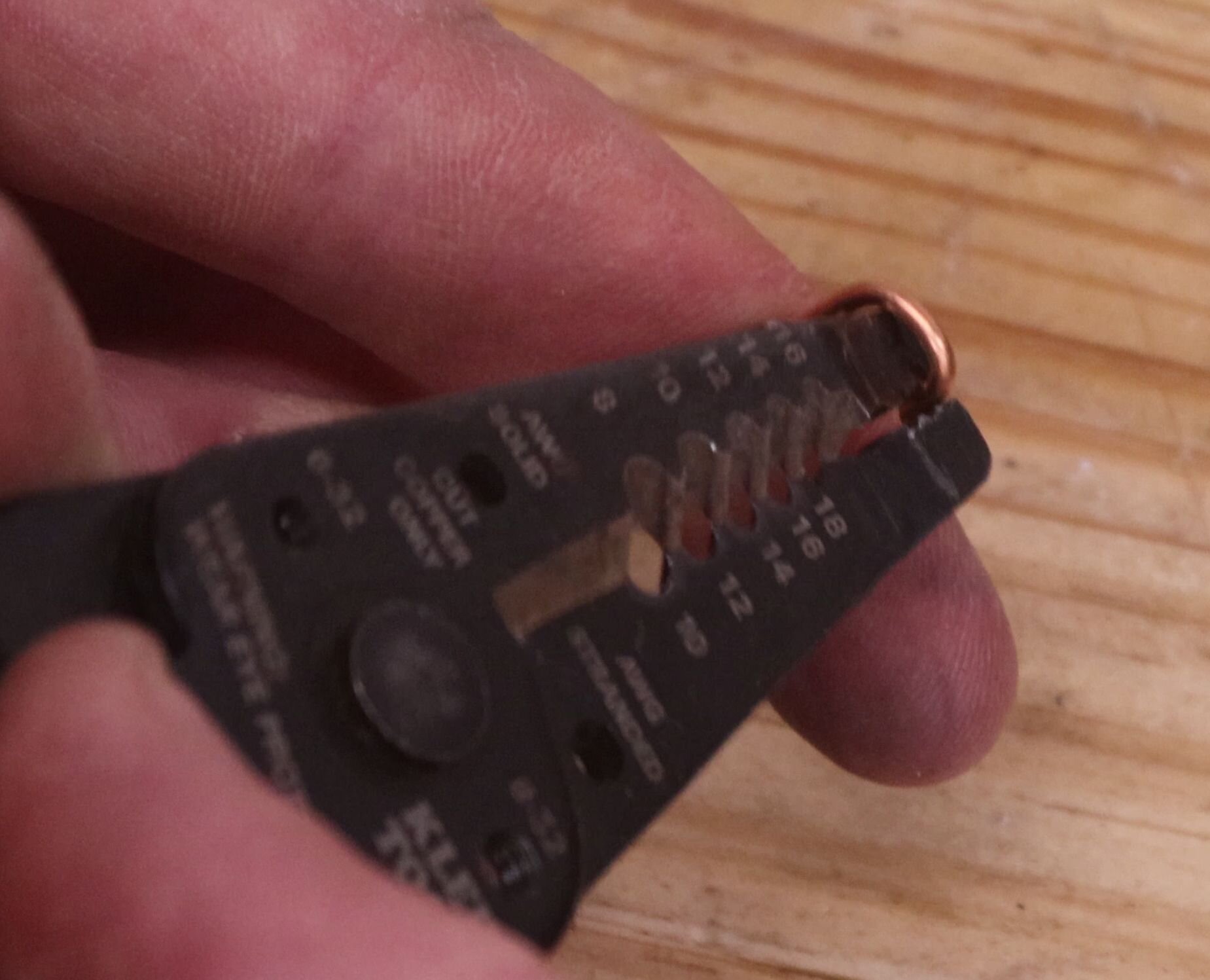
Strip 3/4″ (19 mm) from the other ends of these wires now. Once done, use the wire strippers to bend the ends into hooks.
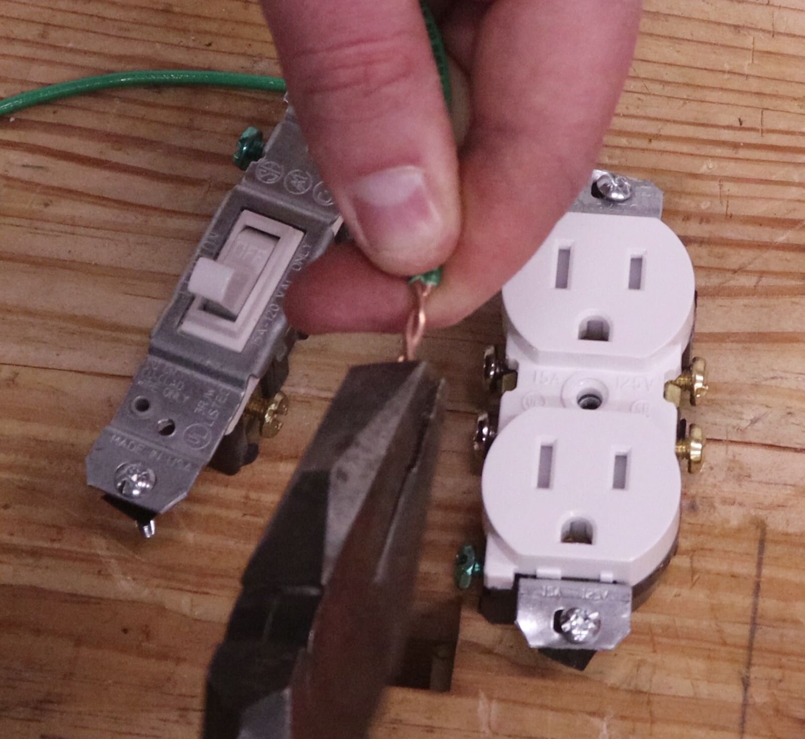
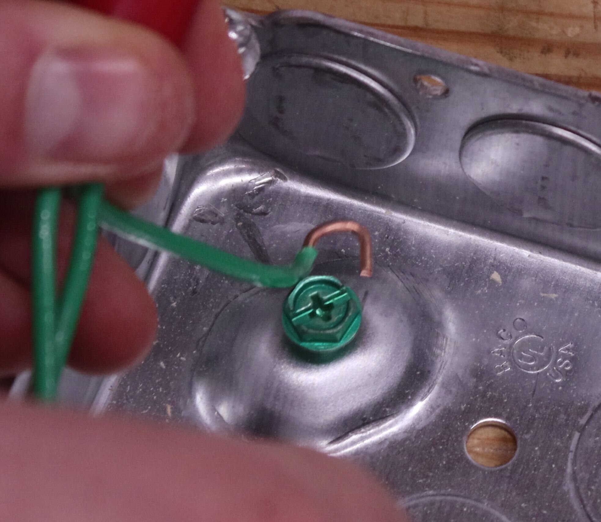
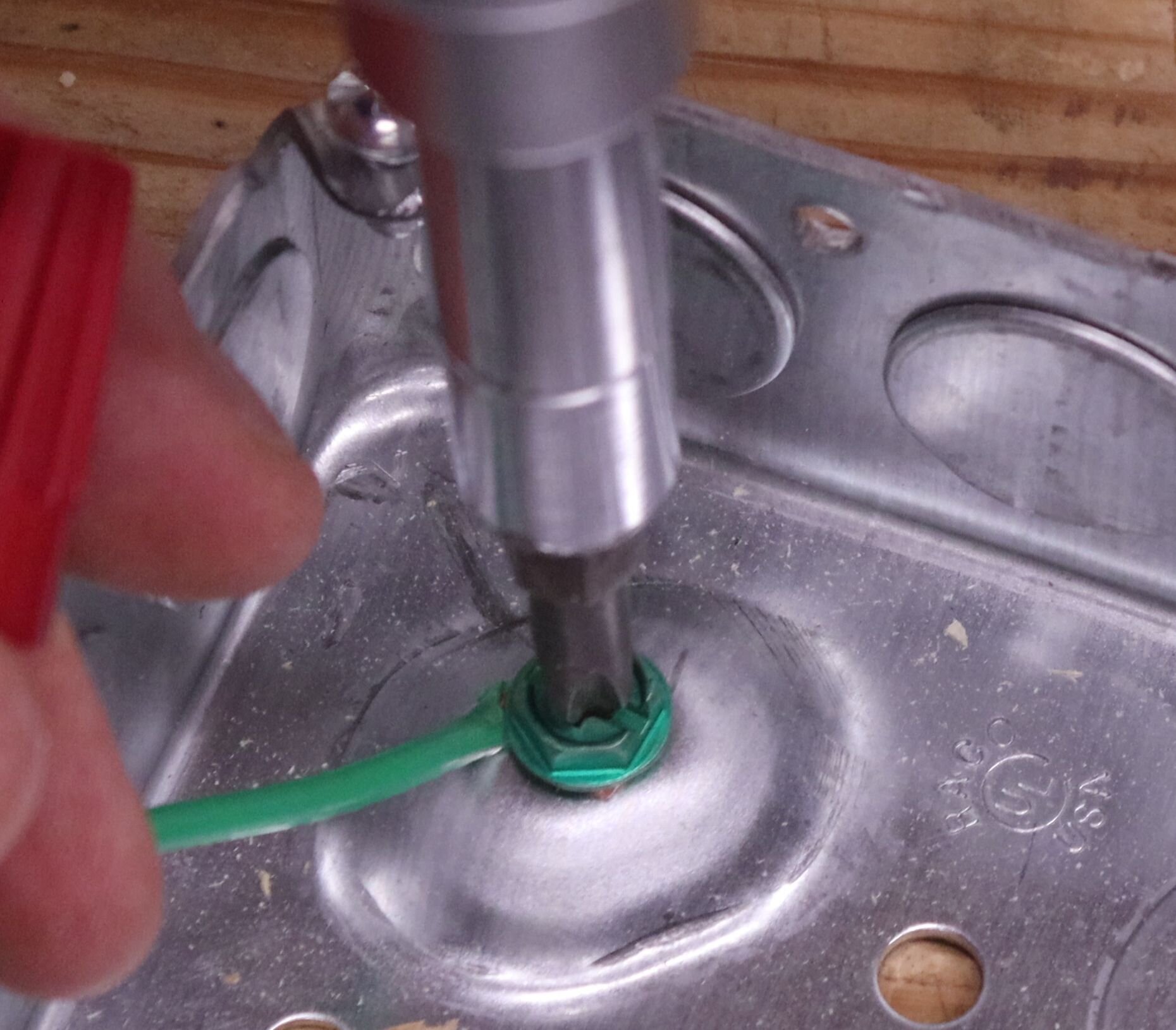
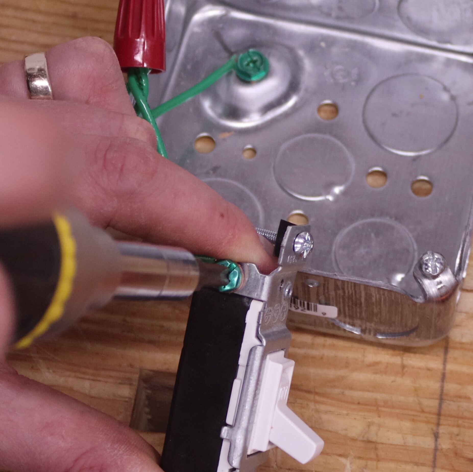
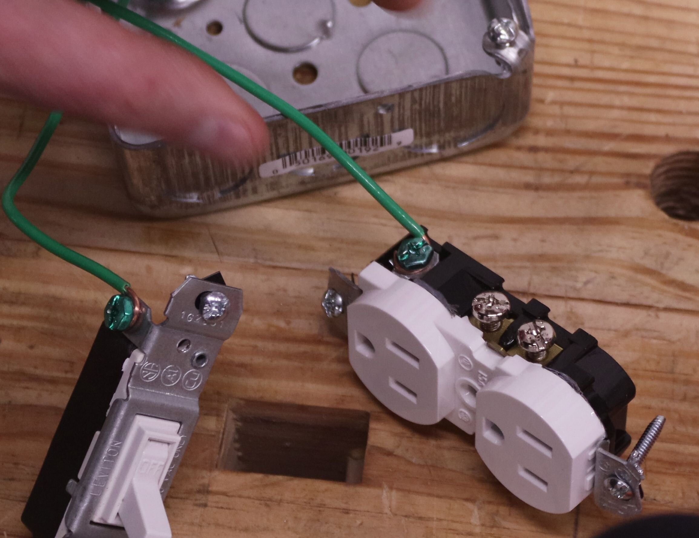
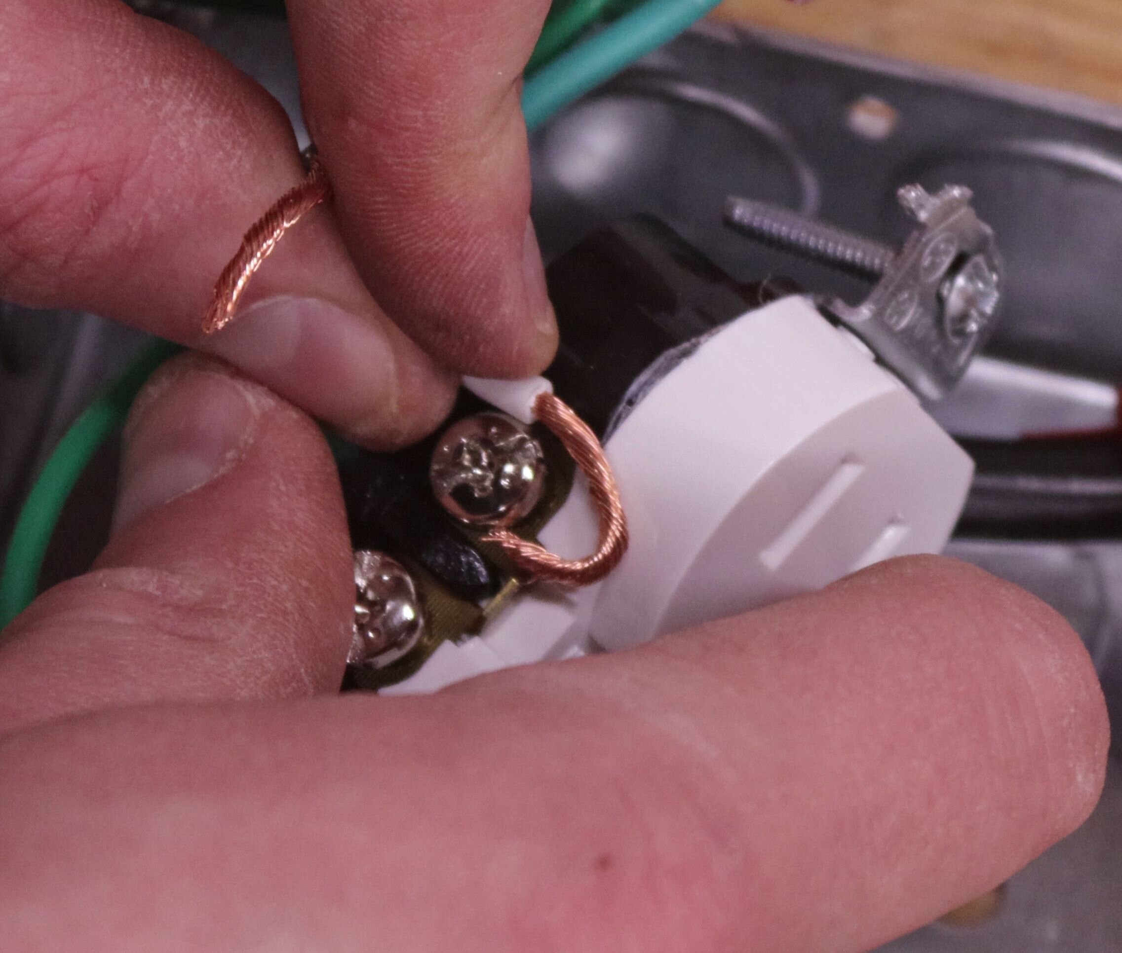
Take the grounding screw and screw it part way into the junction box. Then take one of the hooked wire ends, wrap it around the screw, and fasten it down. Note that the wire is wrapped going clockwise around the screw – this stops the hook from opening up when tightening the screw.
Now is time to attach the ground wire to each of the switch and receptacle grounding screws.
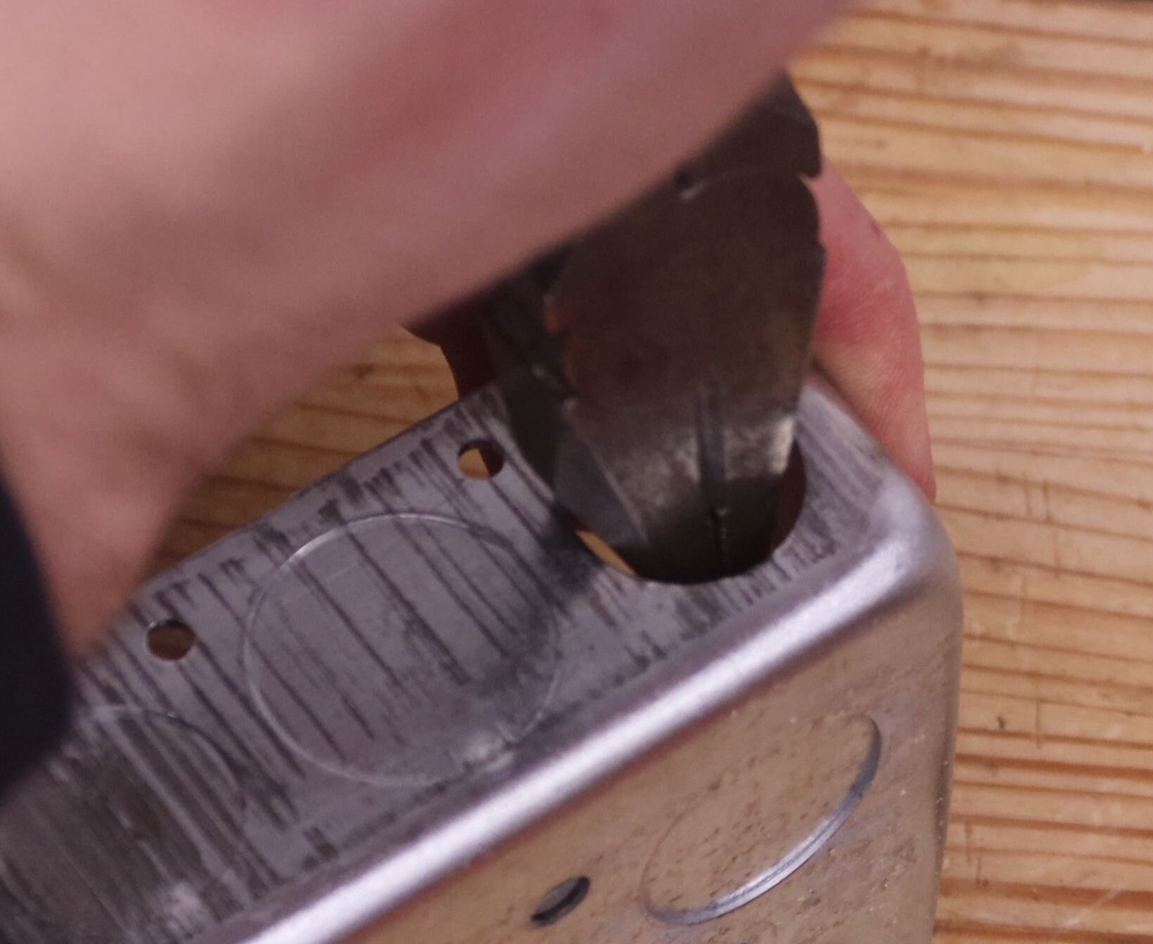
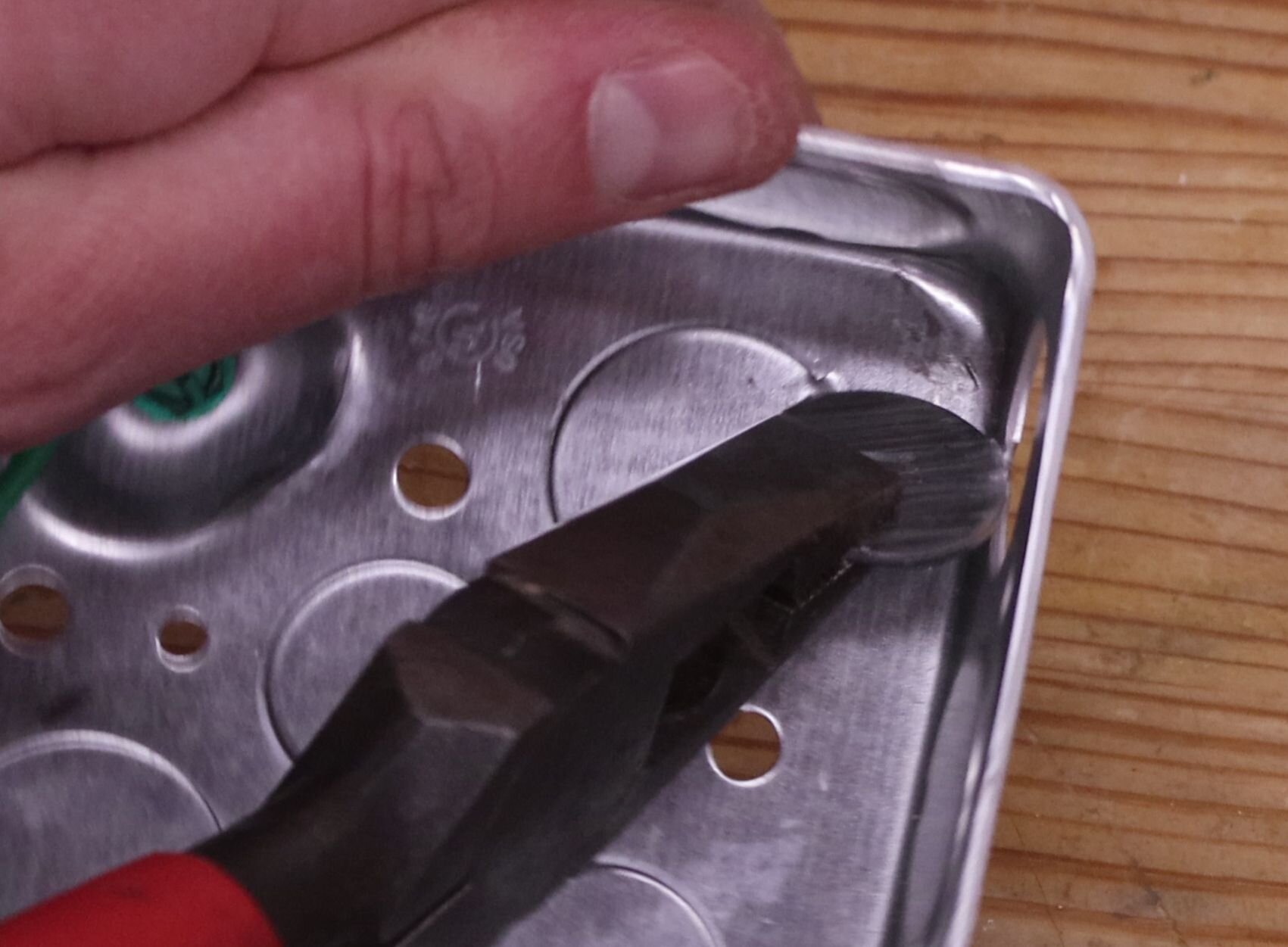
Use the lineman’s pliers to pop out one of the 1/2″ knockouts on the junction box. Just hammer on it until the knockout bends out, then twist it off with the pliers. The power cord will pass through here.
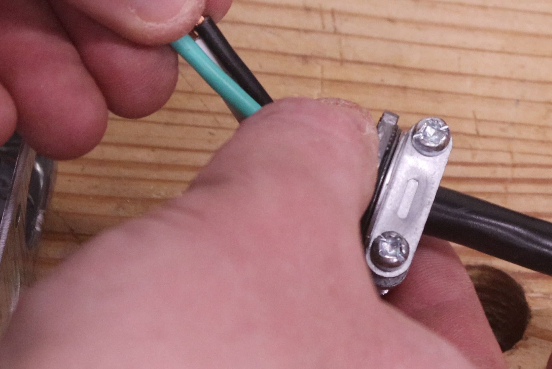
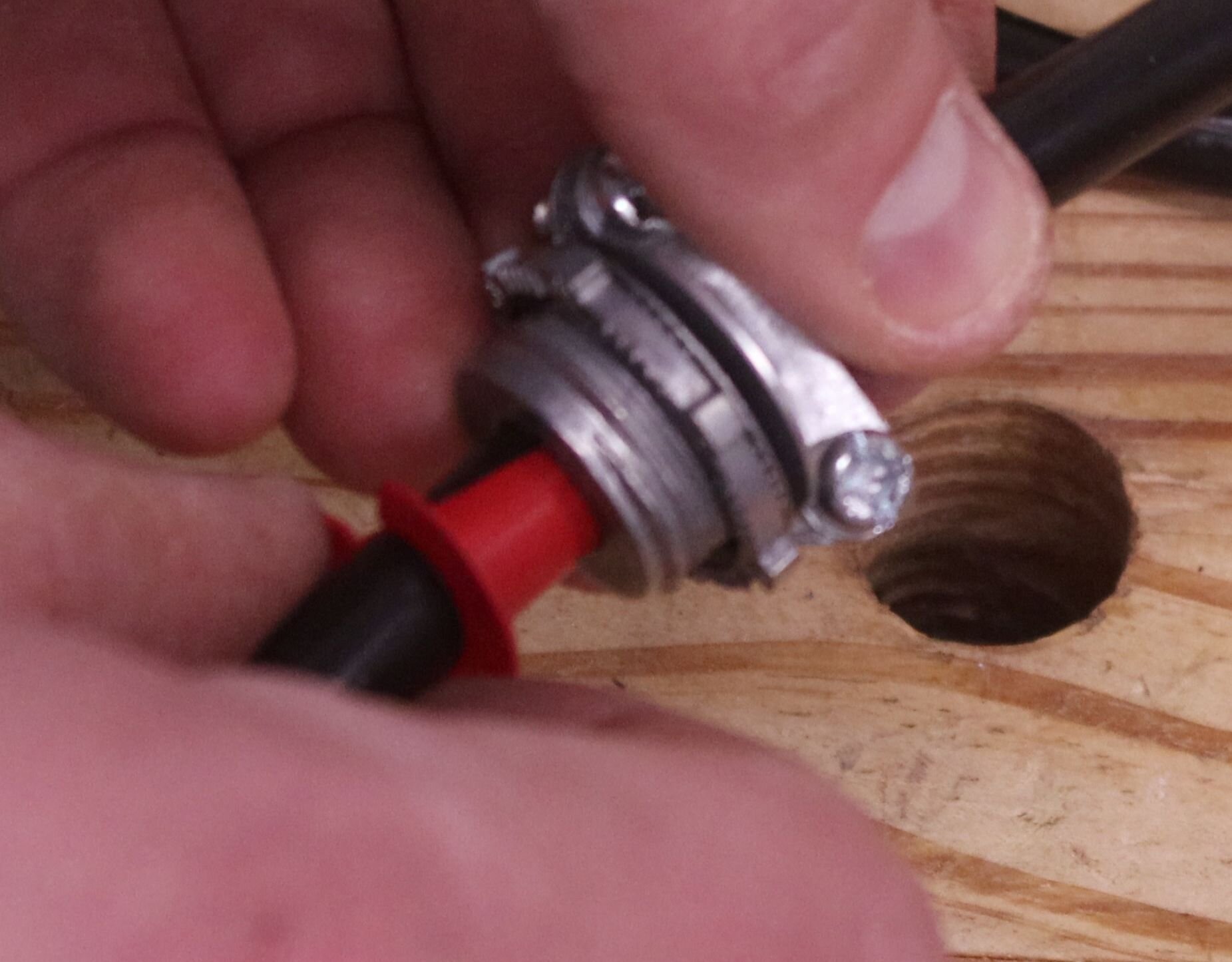
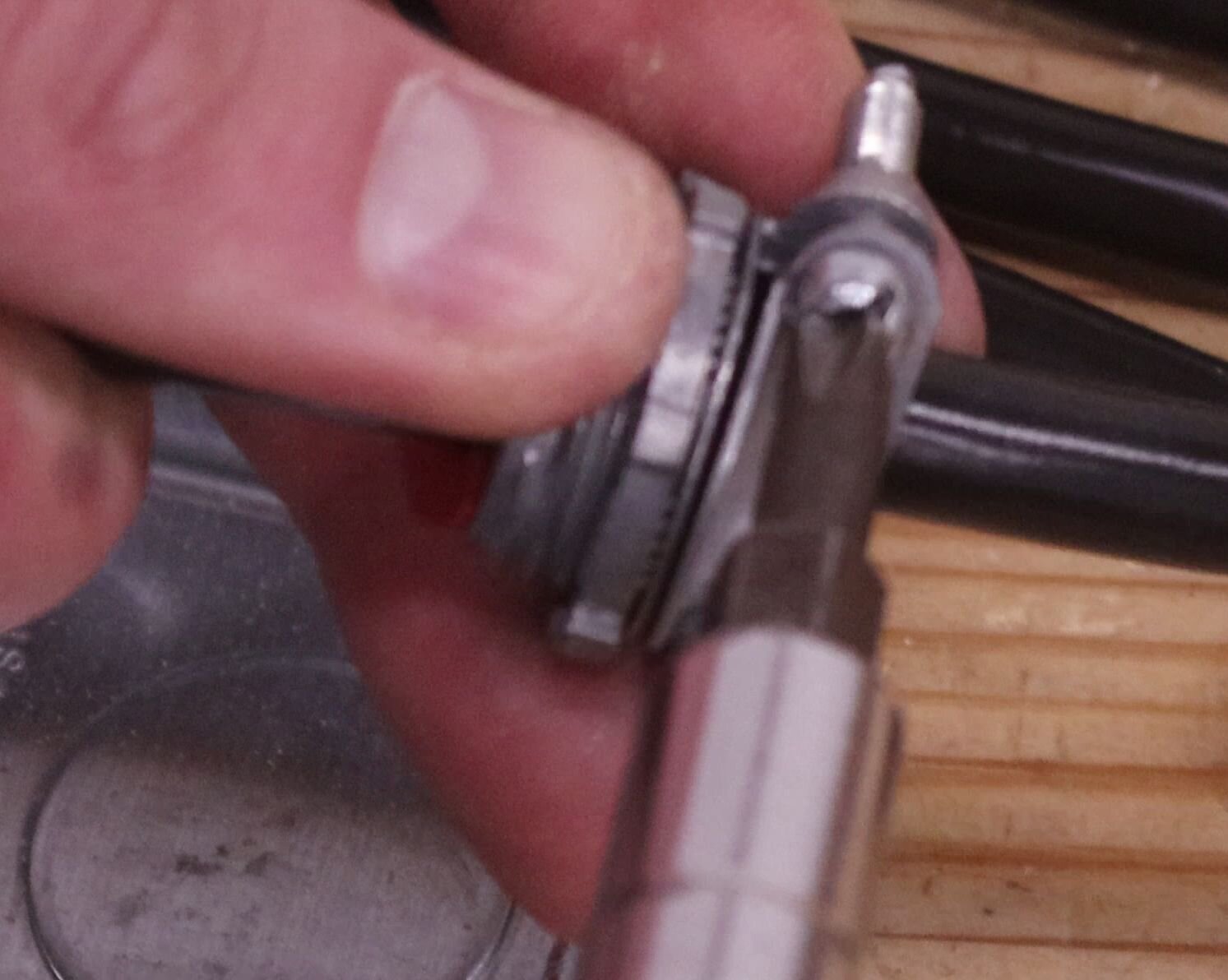
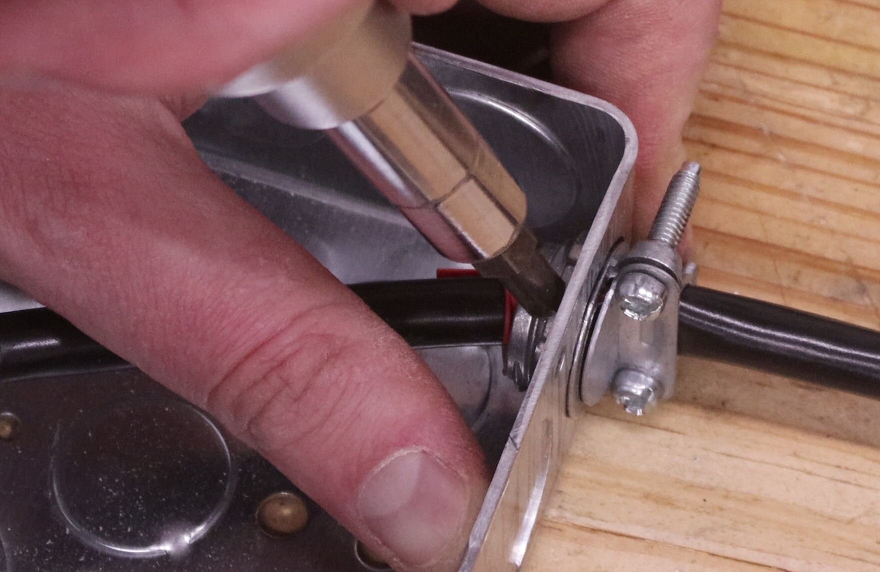
Pull the power cord out of its packaging and slip the clamp connector over the end of it. With the connector in position, also slide the red bushing between the cord and the opening in the connector, and then tighten the screws on the connector. The bushing helps keep the connector from cutting into the wires. Remove the connector’s nut, pass it through the knockout, and thread the nut back into place. The nut can be tightened down by pushing on one of the knurlings with the tip of the screwdriver.
Update: I would recommend a strain relief connector instead of the clamp connector I mentioned above. Installation is much the same as the clamp connector.
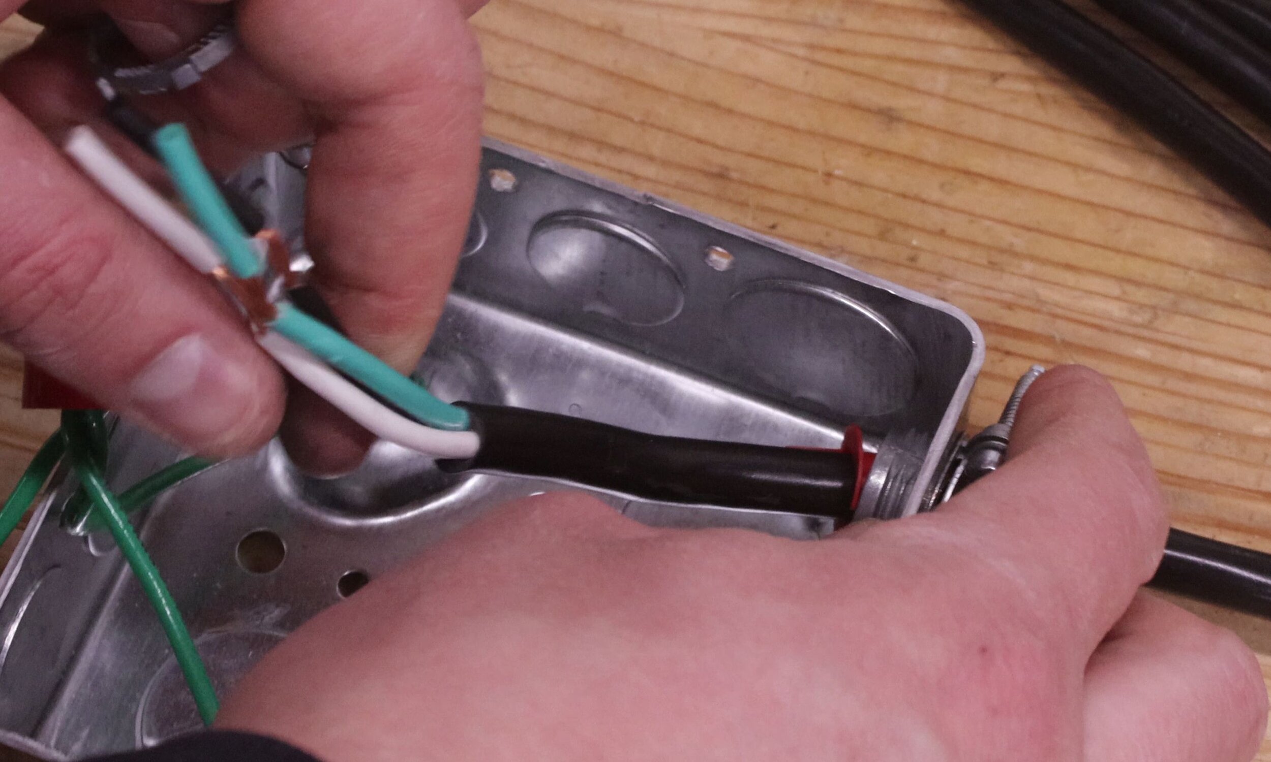
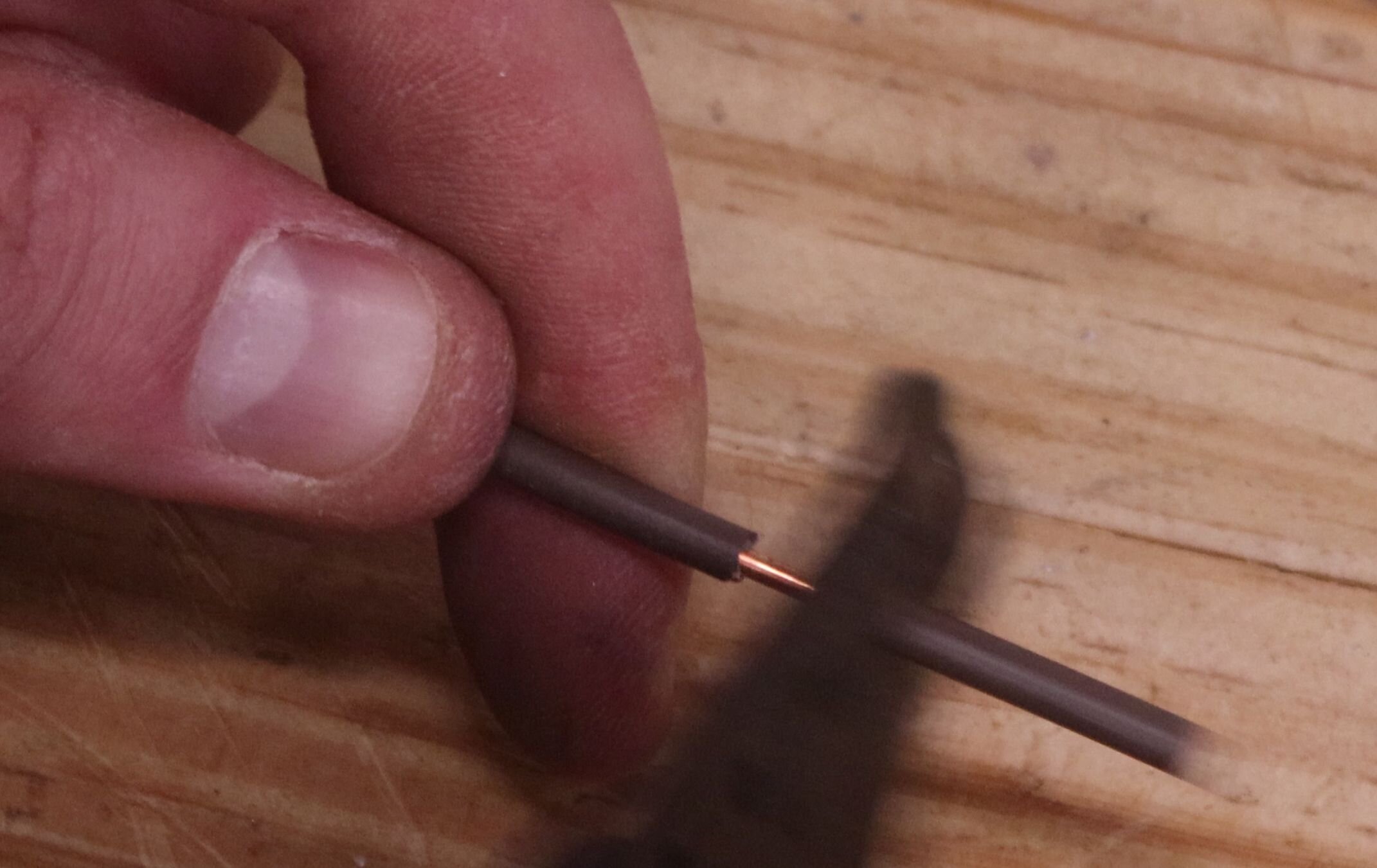
Next strip the ends of the wire from the power cord and twist the strands of the wire tighter. Remove the wire nut from the bundle of ground wires, and wrap the power cord’s ground around them. Fasten the wire nut back down on the ground wires.
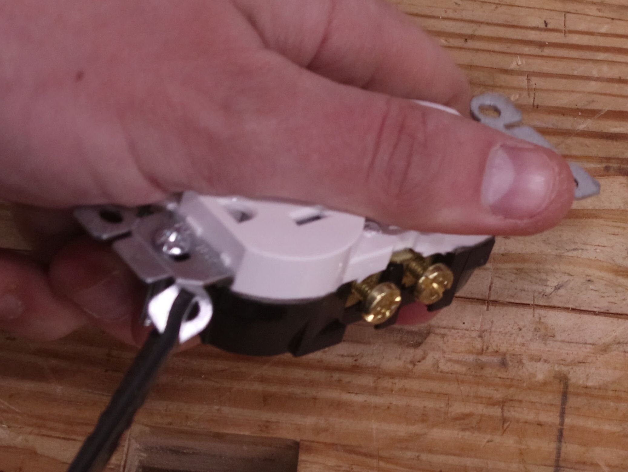
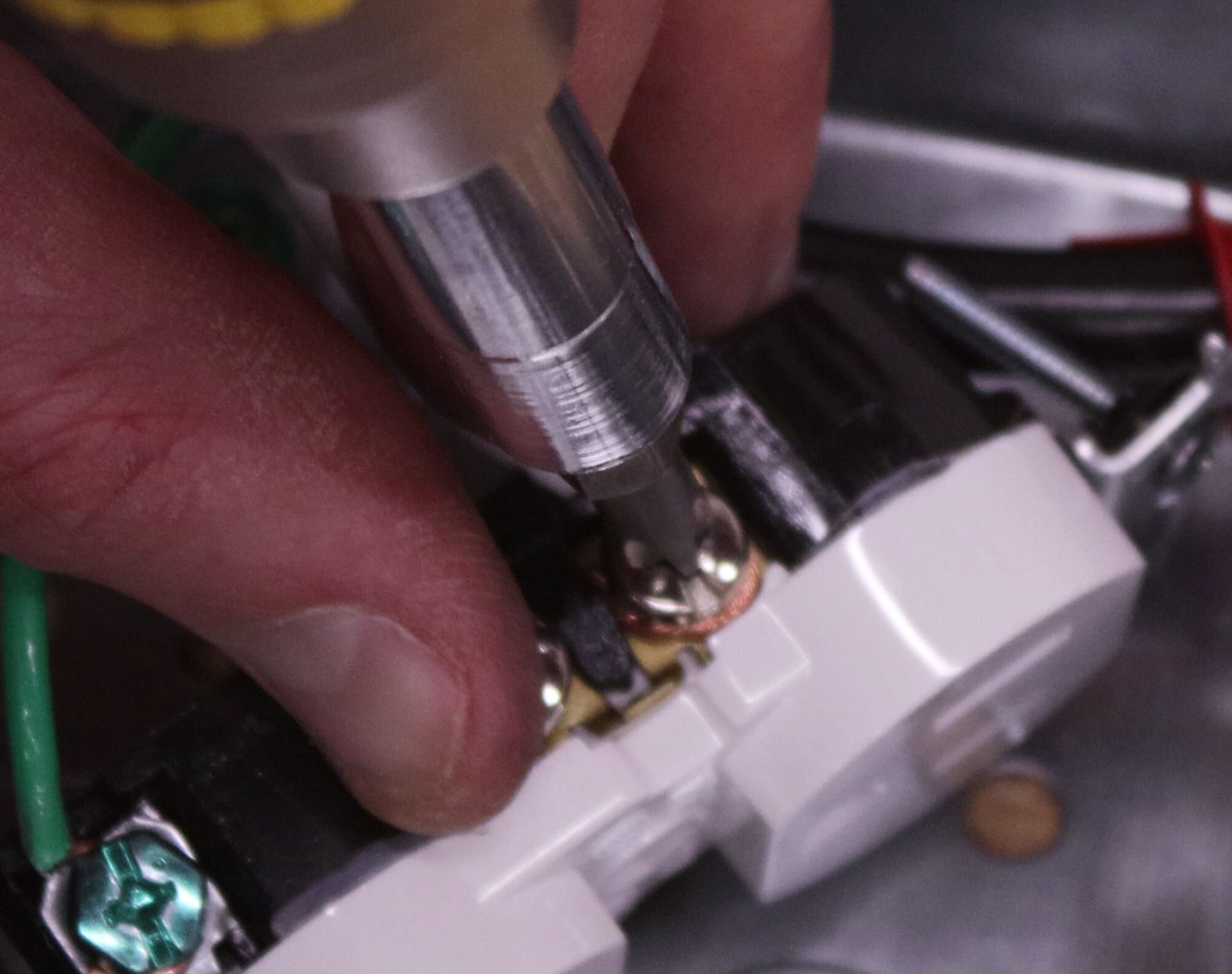
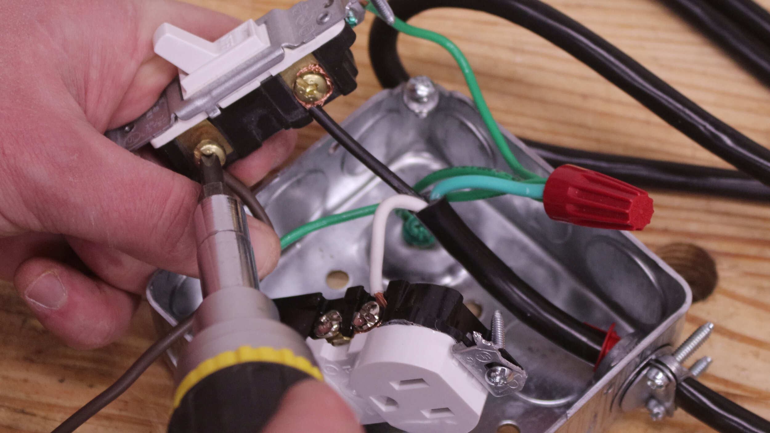
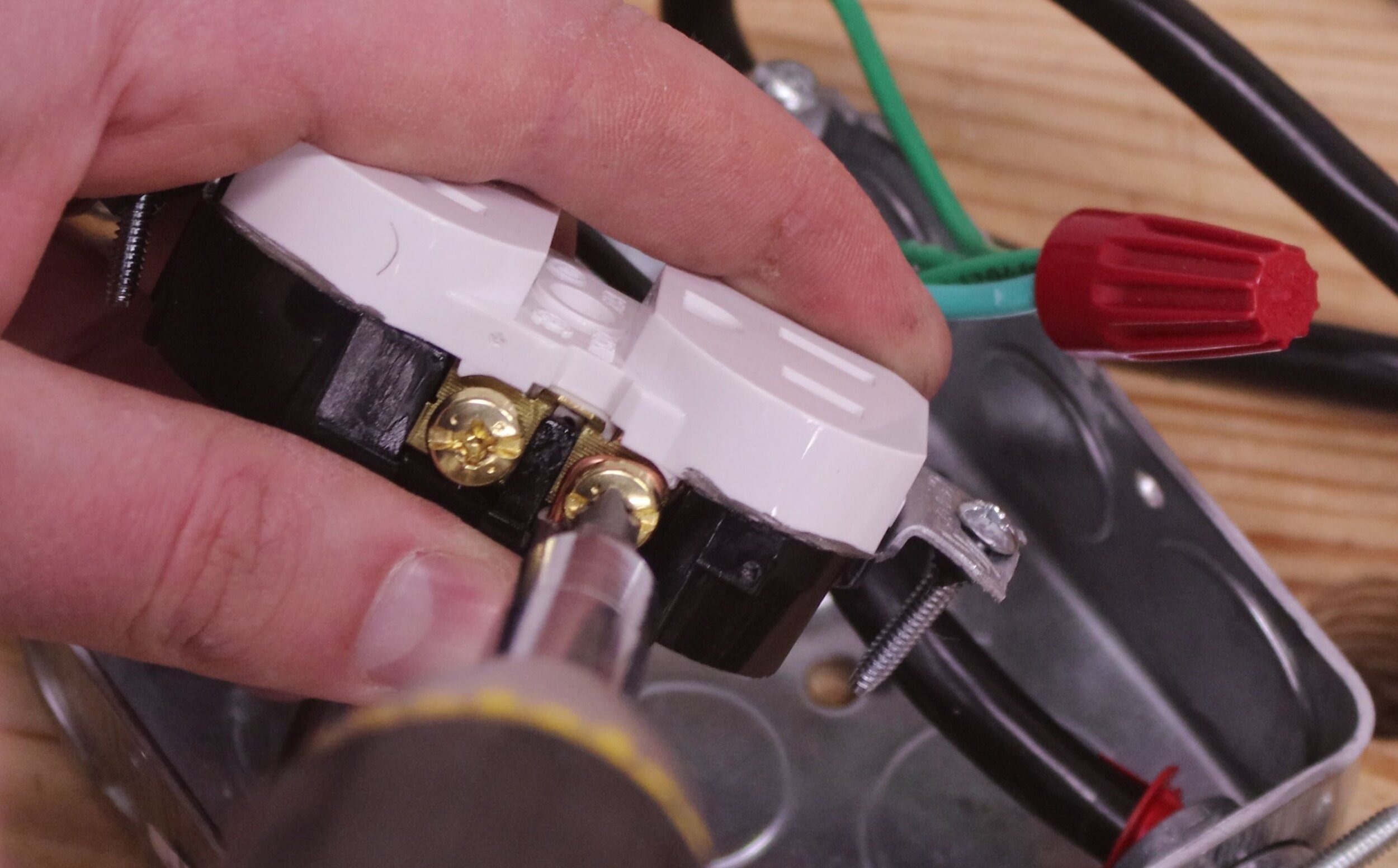
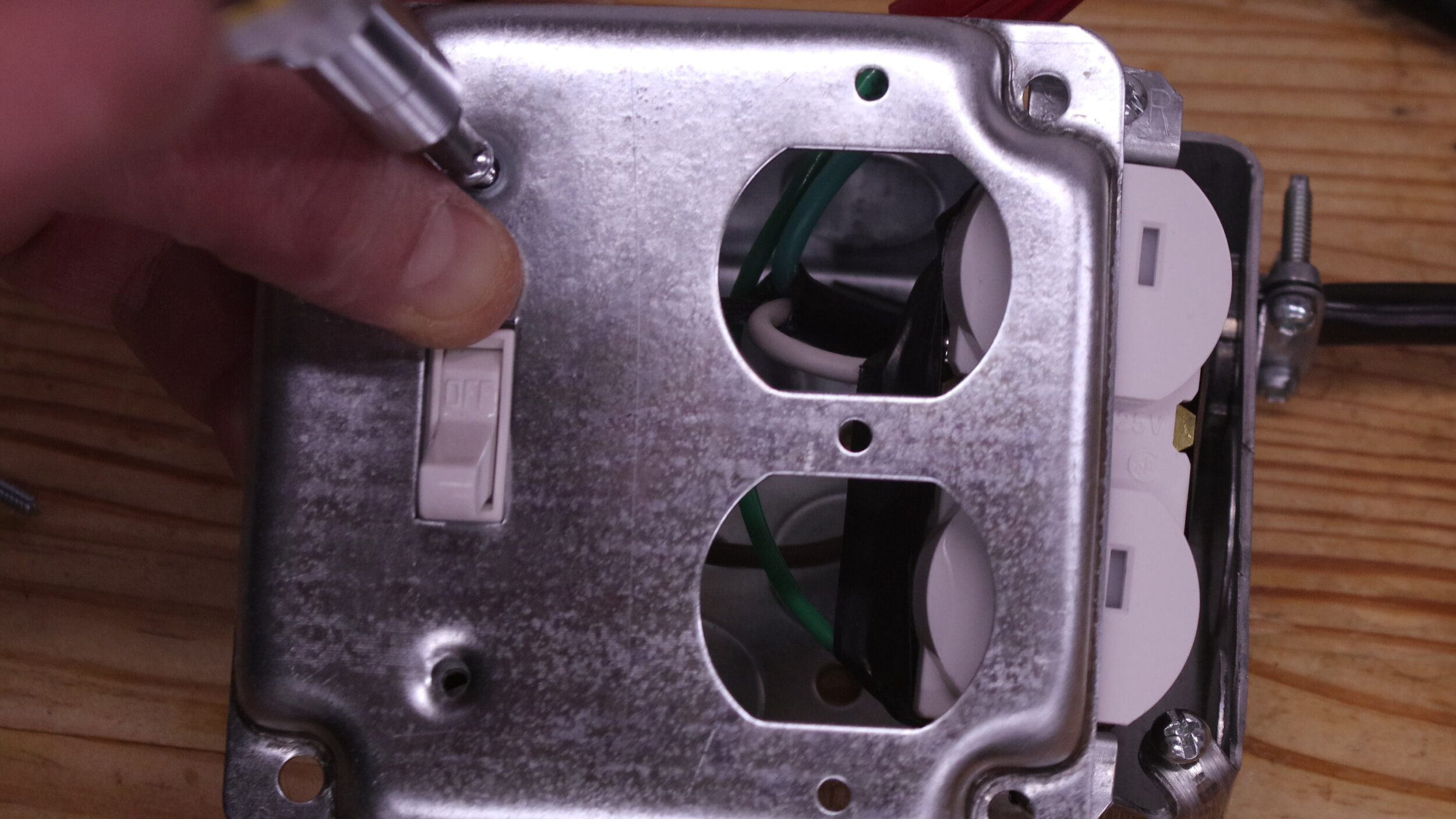
Now to start wiring the switch and receptacle. Start by forming a hook in the white neutral wire from the power cord and wrap this around one of the bright metal screw terminals of the receptacle. Use a screwdriver to tighten the wire down, and also screw in the other terminal to help keep it from shorting out on anything.
Next, take the black hot wire from the power cord and wrap it around one of the terminals on the switch. It doesn’t matter which one. Tighten it down with your screwdriver.
A quick wiring tip: white to bright, black to brass, green to ground is an easy way to remember how to wire an outlet.

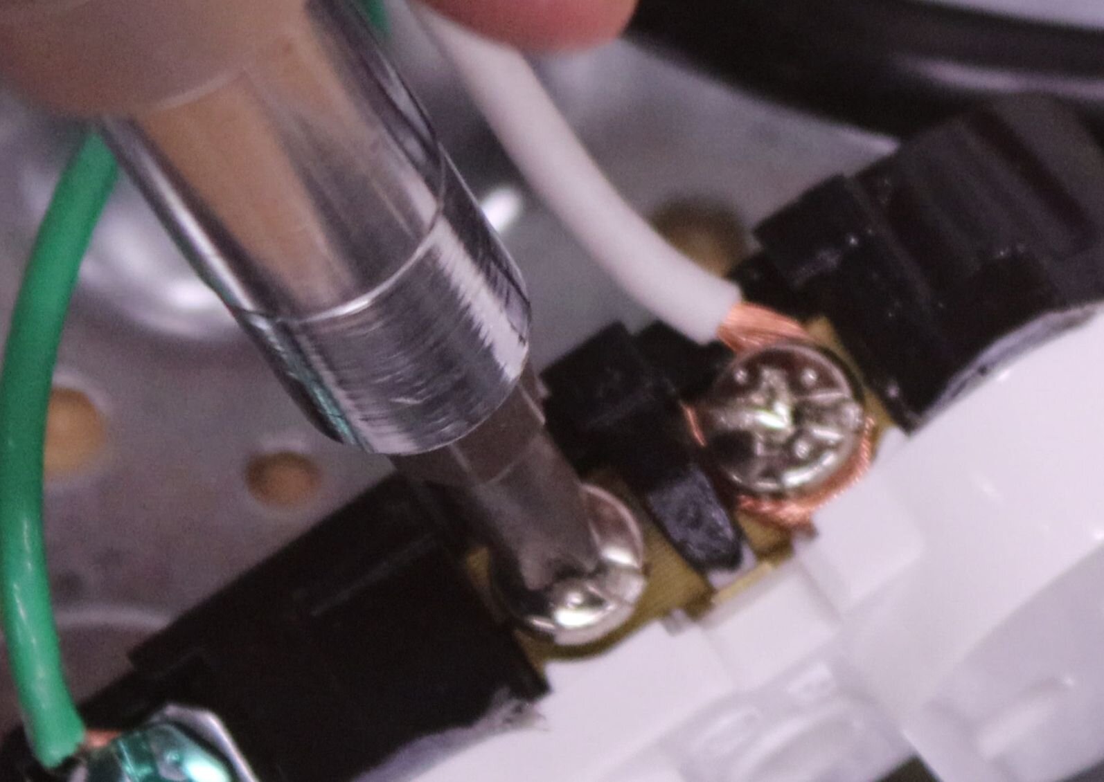
Take out the 6″ (150 mm) length of colored wire and strip 3/4″ (19 mm) off both ends. Using the wire strippers, bend hooks in both ends. Wrap one of the ends around the empty terminal on the switch and fasten it down. Then, take the other end of this wire and attach it to the brass-colored terminal on the receptacle and also fasten it down.
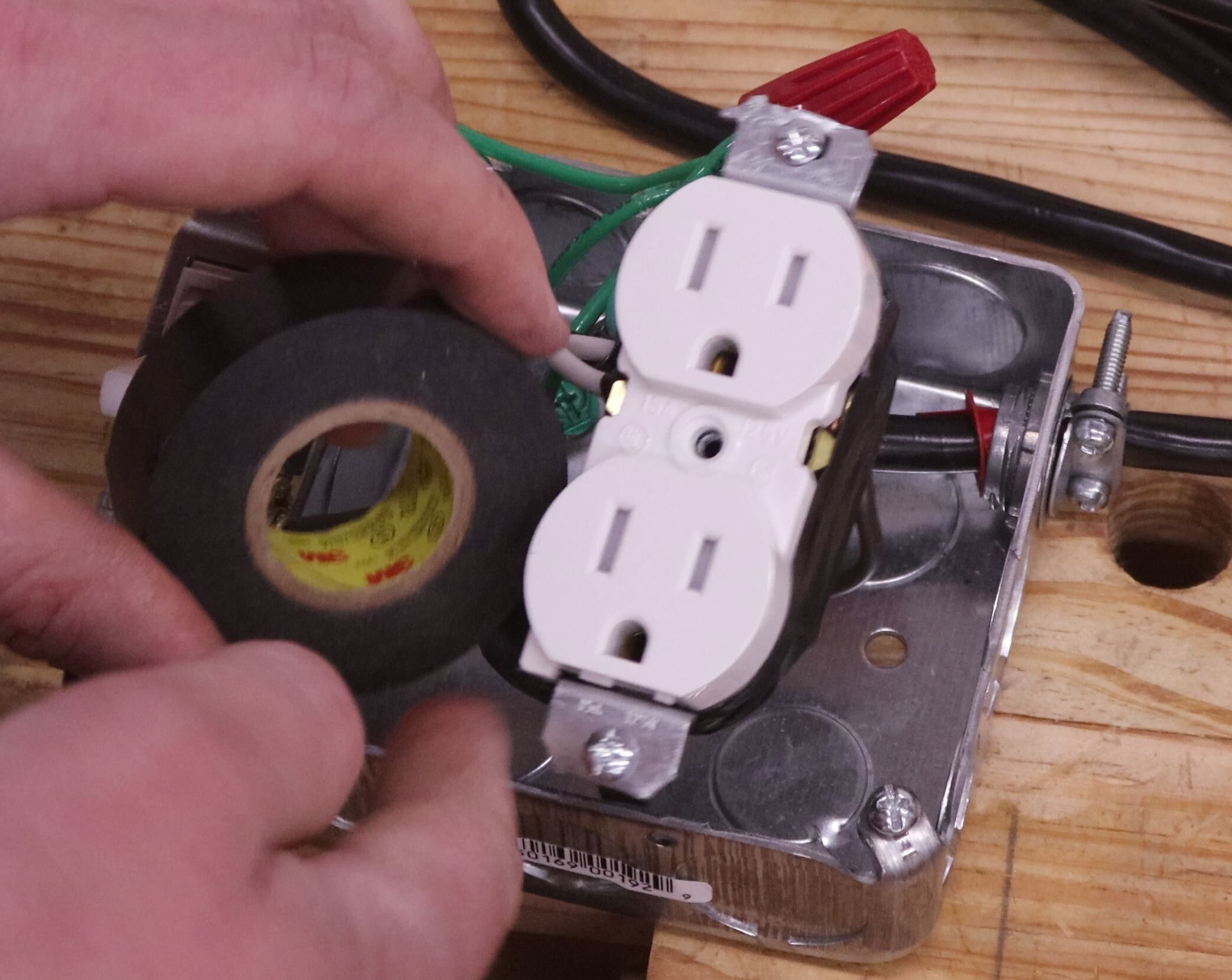
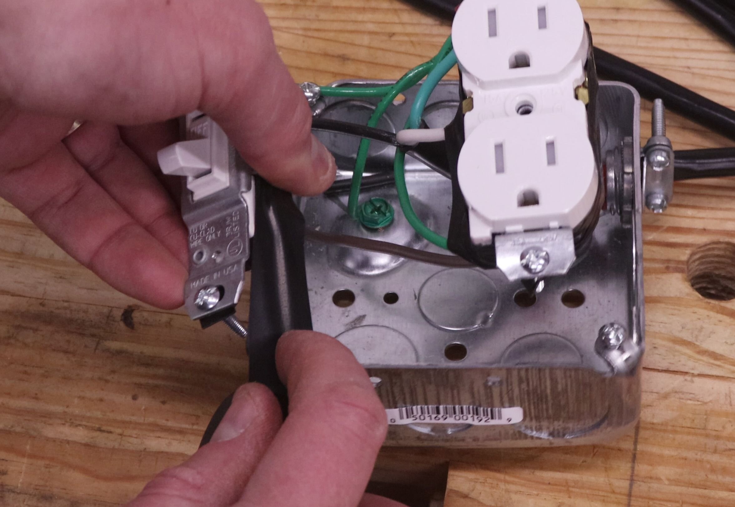
With the switch and receptacle all wired up, wrap both in electrical tape. This helps protect against anything shorting out on the metal junction box or against one another.
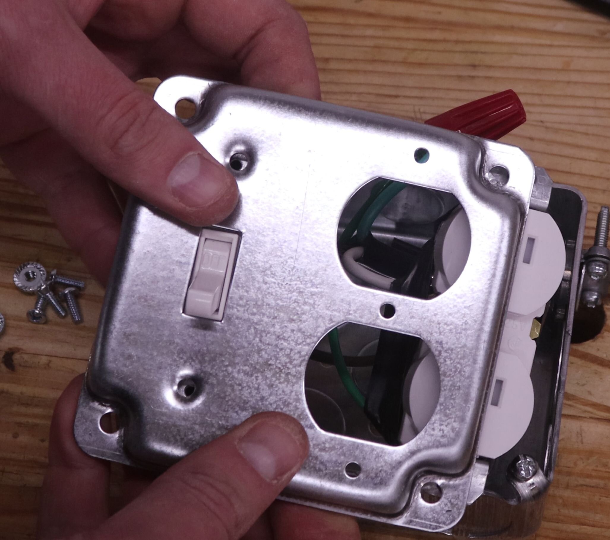
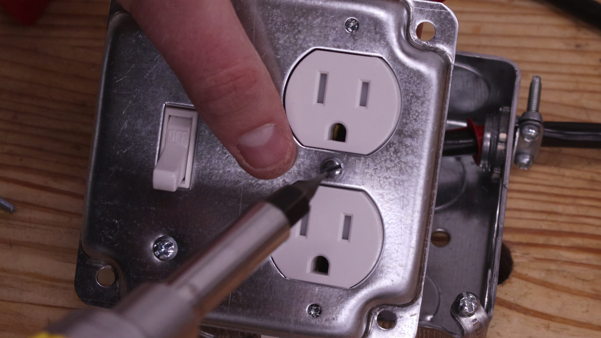
Now to start buttoning things up. Remove the exposed work cover from its packaging. The switch is attached to the cover with the two included screws. For the receptacle, there’s a single screw in the center that fastens it down. Also included are two screws with nuts that can go on the top and bottom of the receptacle, but I don’t find these necessary unless you plan on plugging things into this frequently.
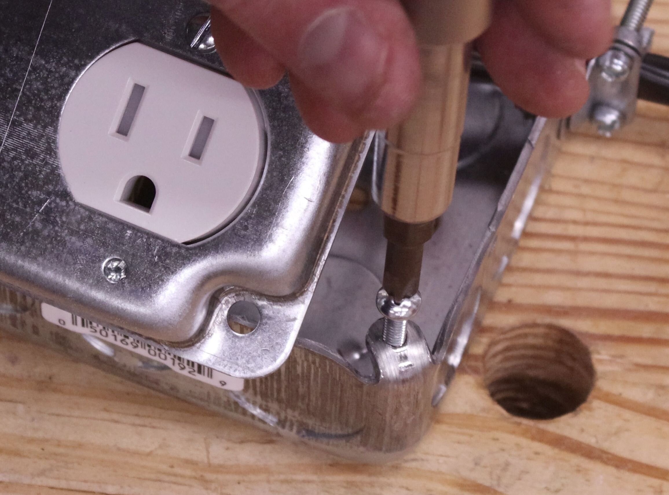
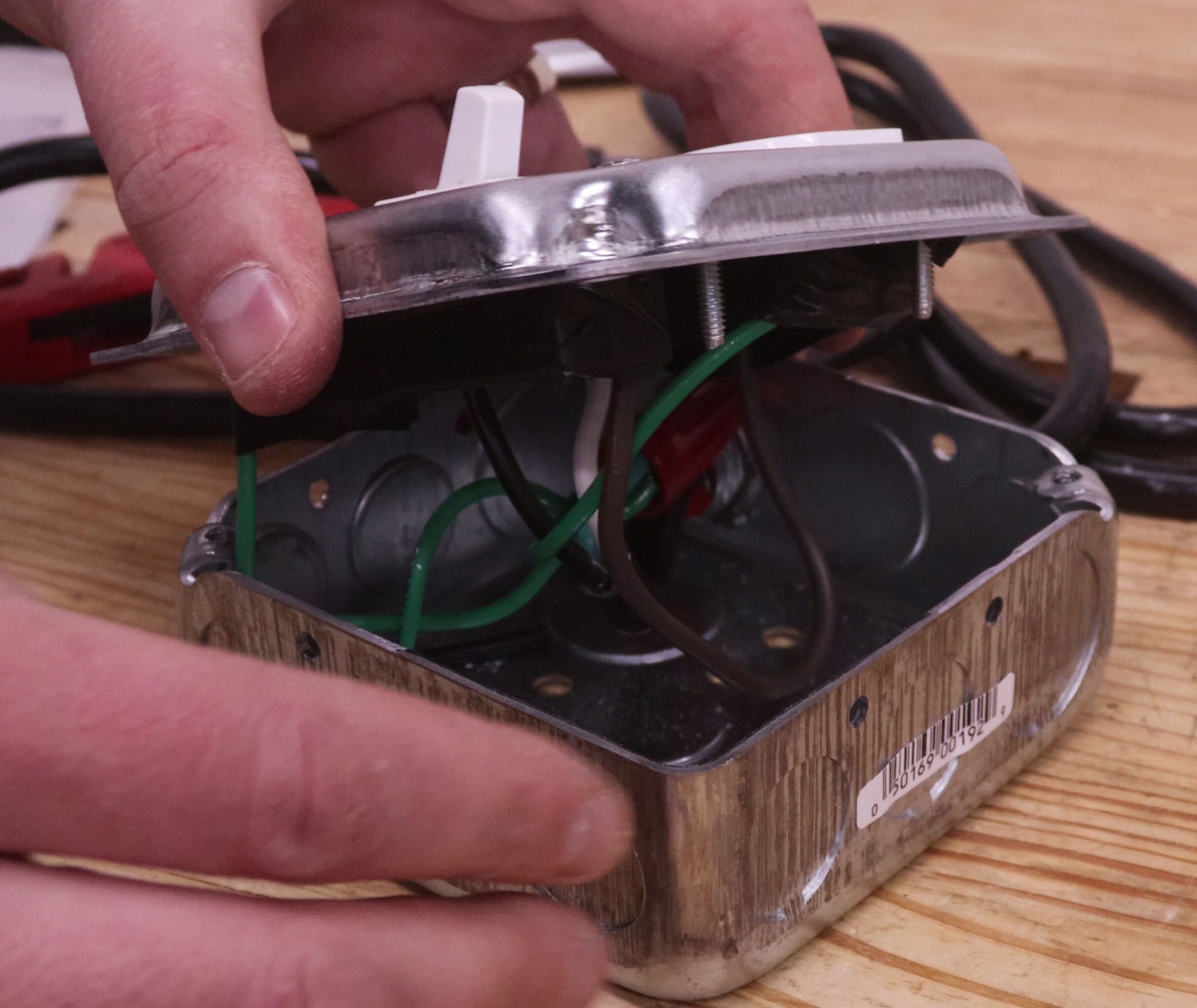
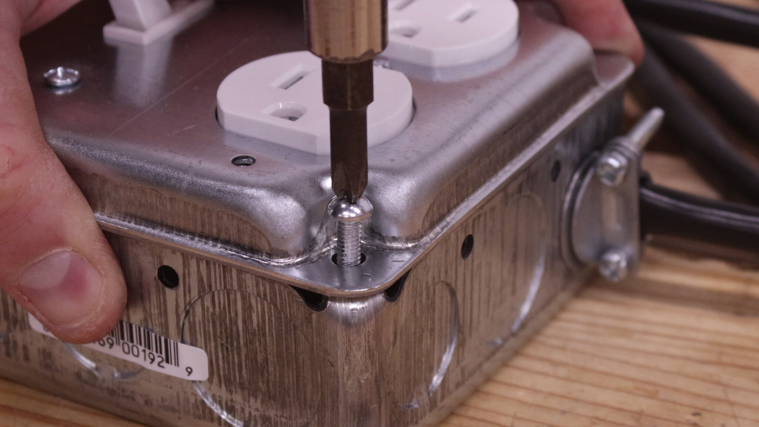
Take off the screws from the corners of the junction box. These same screws are reused to attach the cover. Neatly fold the wires into the junction box, and fasten the cover down with the two screws in the corners. The switched power source is now complete!
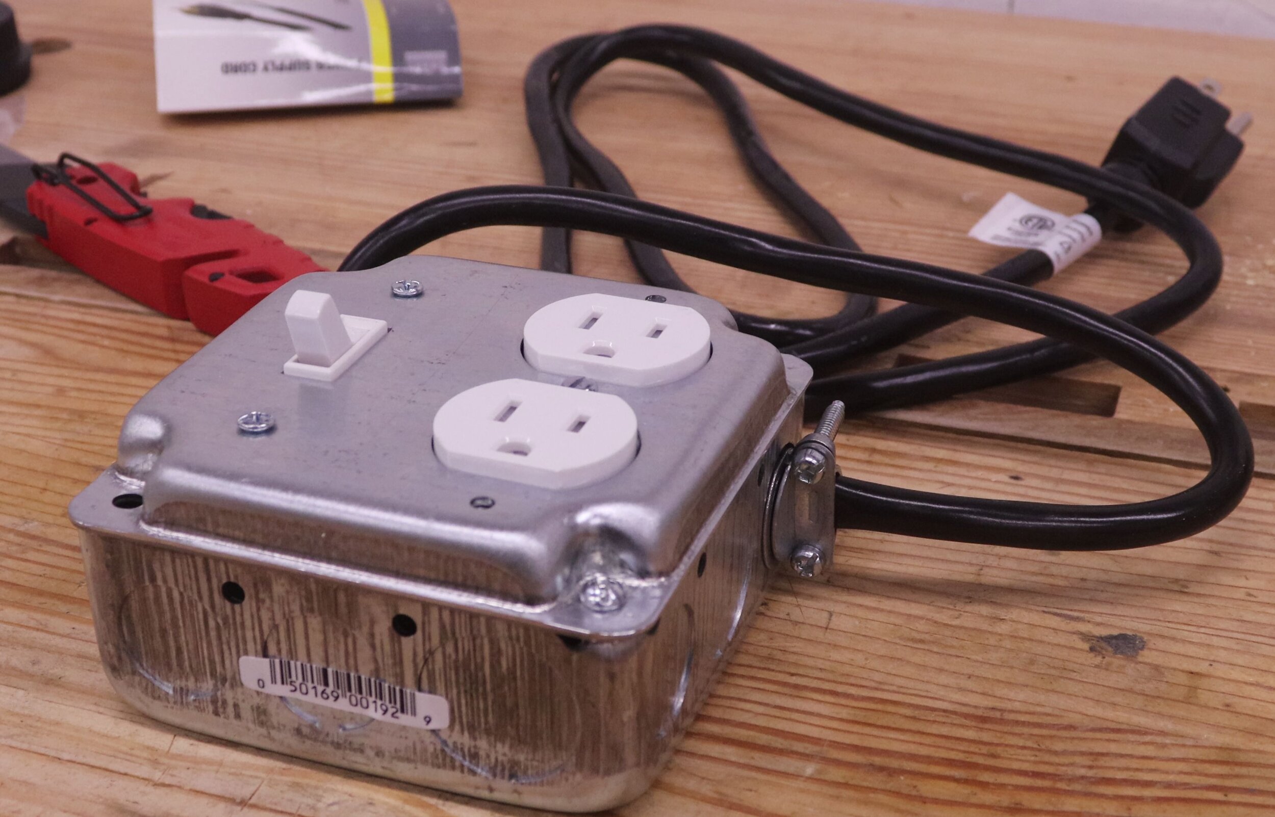
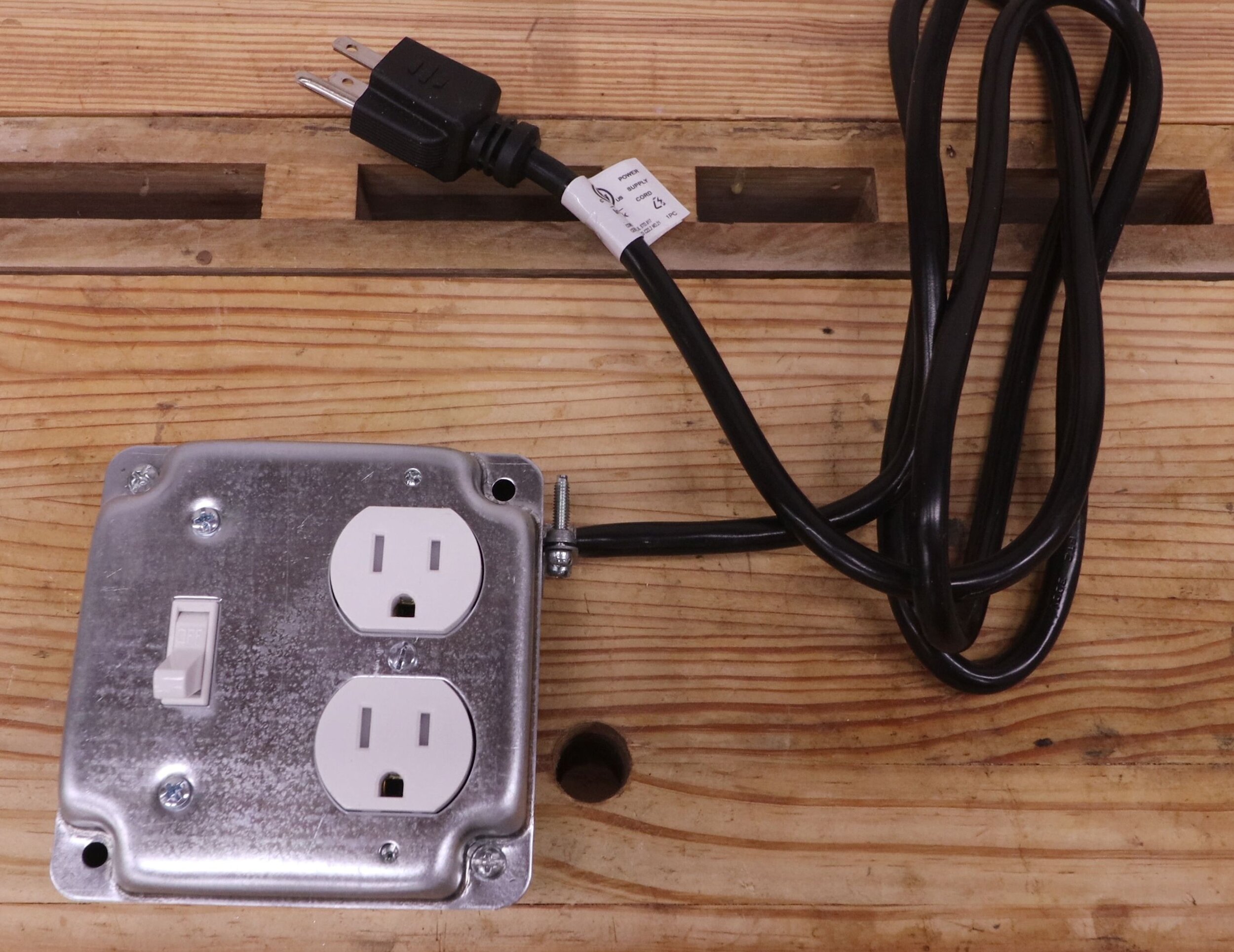
You now have a portable switched outlet, ready to be used in any number of situations. As stated previously, this concept can be easily modified to use a double-switched outlet, or to use a ground-fault receptacle for outdoor applications, or any number of other types.
If you enjoyed this article, subscribe to my YouTube channel for more!
——————————————————————————-
Below is a listing of the supplies and tools you will need to build this. I have supplied Amazon Affiliate links to the products I used. As an Amazon Associate I earn from qualifying purchases.
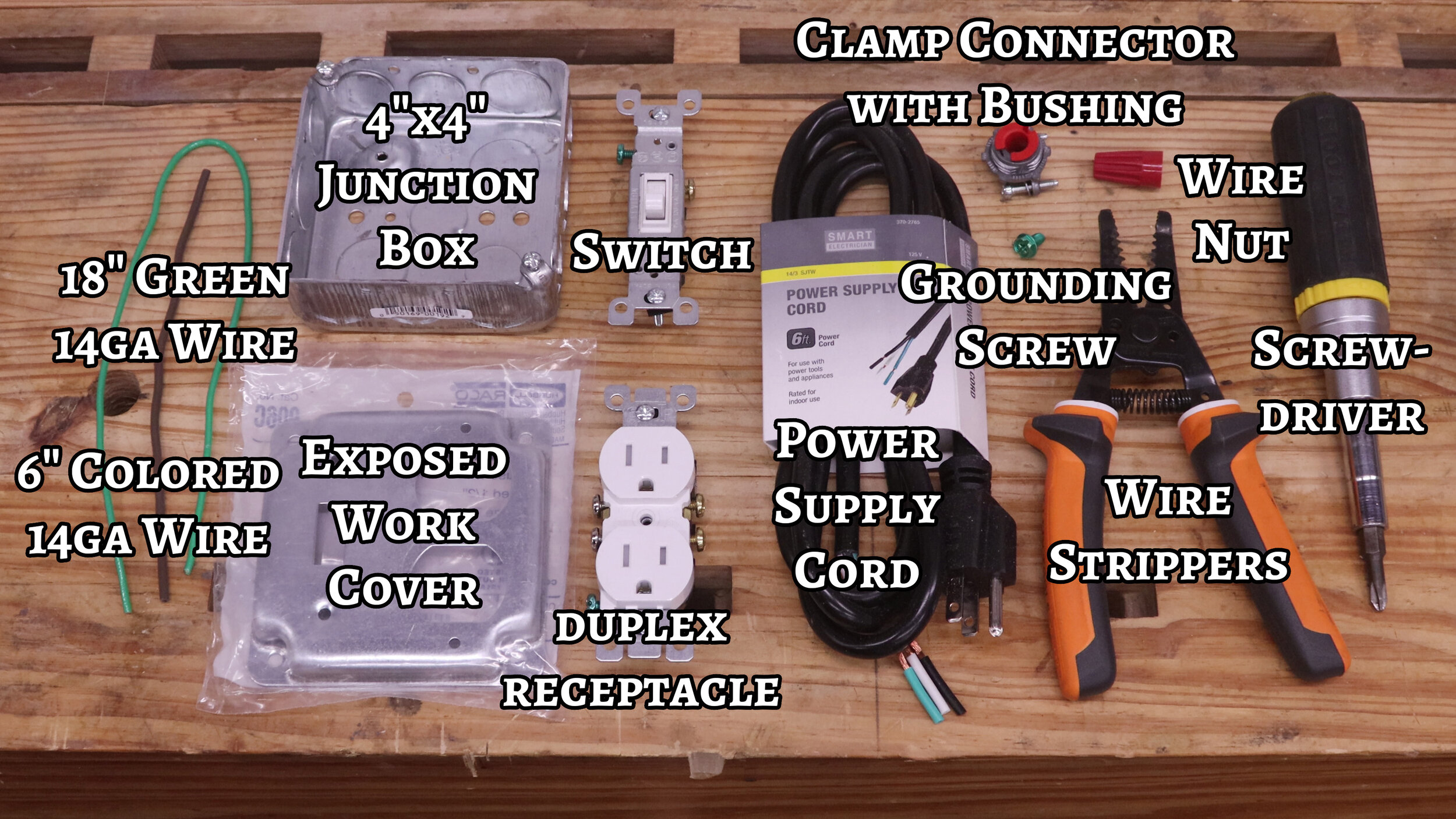
Supplies:
4” by 4” metal junction box with a raised dimple inside for a grounding screw
Exposed work cover, with slots for a switch and a duplex receptacle
Switch (15 amp rated)
14 gauge power supply cord, with ground
18” (450 mm) of green 14 gauge wire
6” (150 mm) of colored 14 gauge wire (doesn’t matter what color, just not white)
Clamp connector and red plastic bushing
Strain relief connector (instead of the clamp connector above if you’re worried about the cord wearing through)
Tools:
Screwdriver(s) with #2 Phillips and flathead tips